 Study Plan
2110 Topo
Study Plan
2110 Topo
What you will learn on this page
This lesson explains how the 2059 Standard fits into the SMPTE ST 2110 stack.
• PTP V/A/TC Phase Alignment
• How it Works
• Timing
• PTP Control Loop
• Profile behavior
• BMCA
• Guidelines on when to use Transparent and Bountrary clocks
• Troubleshooting
• Keeping PTP "Small"
This standard is in two parts.
 ST 2059-1: Defines how to derive broadcast reference signals (video frame/line phase, audio sample phase, and timecode) from a PTP timebase. In other words: how to turn PTP time into the equivalent of house black/tri-level and LTC/VITC alignment.
ST 2059-2: Defines the PTP profile for media facilities: clock roles, message types/behavior, and interoperable defaults so different vendors lock to the same time the same way.
PTP distributes a precise time-of-day clock across your IP fabric. ST 2059 tells media devices how to align their video/audio phases to that clock so every camera, mixer, multiviewer, and encoder shares the same frame and sample boundaries—just like genlock, but over Ethernet.
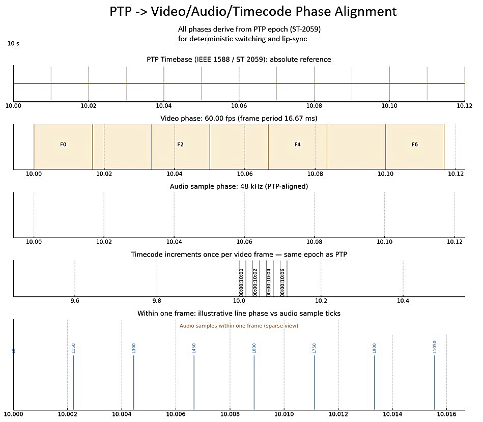
The top line in the graph states that everything in the plant is timed to the same master clock (PTP per ST 2059), so video frames/lines, audio sample ticks, and timecode all reference a single, absolute timebase (the PTP “epoch,” i.e., the common origin for timestamps).
How it Works
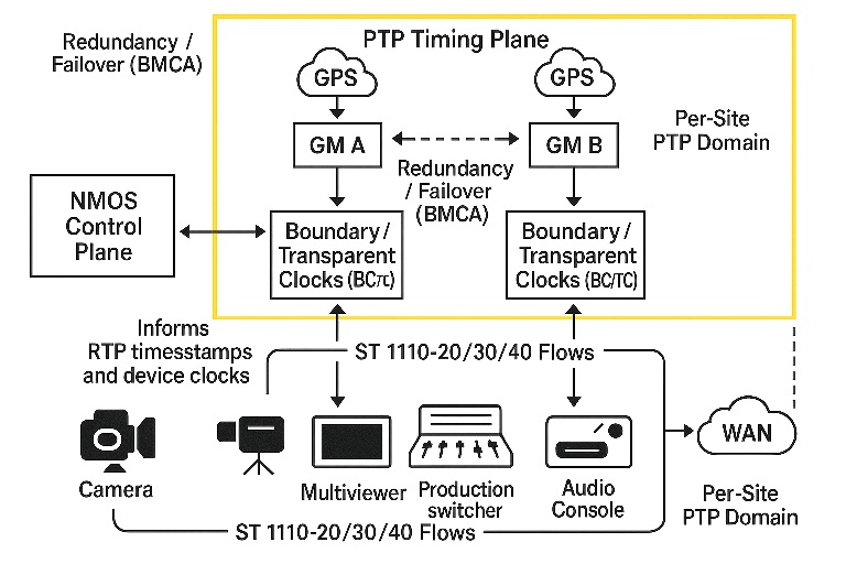
Mock PTP Setup panel- Grandmaster (GM): A GPS/GNSS-disciplined GM (or other primary reference) advertises time across the PTP domain.
- Best Master Clock Algorithm (BMCA): Switches/devices elect the GM automatically and fail over if needed.
- Distribution via network clocks...
- Boundary Clocks (BCs) re-time PTP on each segment (While a slave to upstream ports it is a new master on each downstream port).
- Transparent Clocks (TCs) don’t re-time; they add residence delay into the PTP packet’s correctionField.
- Endpoints lock: Cameras, ST 2110 senders/receivers, audio devices discipline their local oscillators to PTP time.
- Media phase mapping (2059-1): Devices compute exact frame starts, line boundaries, and audio sample ticks from PTP time and align RTP timestamps (e.g., 2110-20 video, 2110-30 audio) to those boundaries.
Important details ST 2059 nails down
We use PTP’s precise time (TAI) as the master clock, and we handle UTC/leap seconds correctly so “wall-clock” time never gets fuzzy...
TAI (International Atomic Time) is a continuous, never-pausing time scale... A leap second is an extra one-second adjustment...
A leap second is an extra one-second adjustment occasionally added to UTC (the civil time we use on clocks) to keep it aligned with Earth’s slightly irregular rotation. When a leap second happens, UTC shows a weird time like 23:59:60 before rolling to 00:00:00. Because TAI never inserts that extra second, there’s a fixed-but-growing offset between TAI and UTC (on the order of a few dozen seconds).
Timing
Because devices derive RTP timestamps, frame boundaries, and audio sample cadence from that shared clock, their phases align predictably—switches and keys are clean, lip-sync holds, and hitless protection (2022-7) can merge legs deterministically. In short: one clock → one schedule → deterministic media behavior.
The clock itself (continuous)
Every device has a hardware oscillator that runs continuously. PTP doesn’t “tick” the time; instead, the device’s servo (phase-locked loop) disciplines its local clock to match the grandmaster. That means you can read time at any instant (e.g., 10.037 456 789 s) — it’s not quantized to 20 ms or any other step.
The PTP messages (discrete, periodic samples)
To keep that continuous clock aligned, devices exchange messages at configurable intervals. Typical (broadcast/2059-friendly) examples you’ll see:
Sync (/Follow_Up): sent many times per second (e.g., every 125 ms ⇒ 8 Hz; sometimes 62.5 ms ⇒ 16 Hz; sometimes 1 Hz).
Announce: slower, e.g., once per second (or 2 s), for BMCA/leader election.
Delay_Req/Delay_Resp: slaves probe path delay periodically (e.g., 1–4 per second).
Those messages are like measurement samples. Between samples, the servo predicts and smooths using the oscillator, so the timebase remains continuous; the next message nudges it to correct tiny drift and jitter.
Why it can look “frame-like”
A video frame period (e.g., 50 Hz ⇒ 20 ms, 59.94 Hz ⇒ ~16.683 ms, 60 Hz ⇒ 16.667 ms) is unrelated to PTP message timing. If you saw “regular 20 ms,” that was almost certainly a video frame cadence, not the PTP clock.
Bottom line:
PTP time = continuous.
PTP messages = discrete, tunable sample rate used to discipline that continuous time.
PTP Control Loop
PTP isn’t a “stepped” clock—it's a control loop that disciplines each device’s local oscillator (PLL/servo). And yes, a servo needs samples (timestamps) at some rate to estimate and correct phase (and frequency) error.
Here’s the mental model:
Local clock = continuous. Your NIC/CPU has a free-running oscillator. It can tell time at any instant; it just drifts without discipline.
PTP provides samples of “true time.”
A Sync (plus Follow_Up in two-step) gives you the grandmaster send time t₁ with hardware precision.
Delay_Req/Delay_Resp (E2E) or peer-delay (P2P) plus switch correctionField (TC/BC) let you estimate path delay so you can align to the GM’s phase at your port.
Servo math (inside your device):
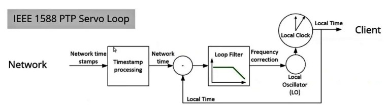
Compute phase error: (GM time at my port) – (my local time) from each Sync sample.
Estimate frequency error (drift) from the trend of those phase errors over time.
Adjust the local clock: nudge its frequency and apply gentle phase slews to drive error → 0.
Message rate vs “continuous time”:
Messages are discrete—e.g., Sync every 125 ms (8 Hz), 62.5 ms (16 Hz), 1 s (1 Hz), etc.
Between messages, your local clock runs continuously; the servo predicts using its oscillator, then corrects on each new sample.
Phase before frequency?
A single precise Sync sample + delay estimate gives you an instantaneous phase error (how far off you are “right now”).
Multiple samples over time reveal frequency error (slope), letting the PLL center its rate so phase doesn’t wander back out.
One-step vs two-step:
One-step: the final timestamp is written into the Sync on egress.
Two-step: Sync goes out, then Follow_Up carries the exact hardware send time. Either way, you get accurate t₁ for the phase measurement.
Why not make the rate huge?
Higher Sync rates improve tracking in noisy networks, but cost bandwidth/CPU and can amplify jitter if the servo is too “stiff.”
Lower rates rely more on oscillator quality. Broadcast profiles pick rates that balance stability, load, and jitter tolerance.
Bottom line:
You do need PTP timestamps at some finite message rate to feed the servo.
Those samples let you measure phase (and infer frequency) error.
The local clock stays continuous; the servo keeps it aligned to the GM between samples.
Profile behavior (2059-2):
- How devices “talk time” the same way.
We pick message settings for PTP (the little time packets called announce, sync, follow-up, and delay). Different brands can use slightly different defaults, but the goal is simple: everyone speaks the same timing dialect so clocks line up. - Agreeing on “who’s the boss clock.”
BMCA is just the election process that picks the best clock as leader. We also set a “domain” number (think: a channel) and a few extra tags so all the gear joins the same timing group and agrees on that one master clock. - Turning clock time into video and audio timing you know.
ST 2059-1 explains the math to turn that master clock into exact video frame and audio sample timing—covering familiar rates like 59.94, 29.97, 23.98, 50, 25, 60, and 24—and it shows how that lines up with SMPTE timecode.
Translation: one master clock in the plant → clean cuts, solid lip-sync, and timecode that matches what you see and hear.
Why this equals “IP genlock:”
- Then (SDI/analog): A house sync generator sent black/tri-level to every device; frame boundaries naturally coincided.
- Now (IP/2110): PTP replaces that electrical reference. Every device computes the same boundaries from the same clock, so switching, keying, and lip-sync are deterministic—without frame-syncing everything.
Practical deployment tips
- Use BC/TC-capable switches and place BCs at aggregation edges to contain jitter.
- Redundant GMs (holdover oscillators) in separate failure domains; let BMCA manage switchover.
- Keep profiles consistent (don’t mix 802.1AS/gPTP with ST 2059 on the same timing plane).
- Minimize asymmetry (fiber path differences) and prioritize PTP with QoS/CoS.
- One PTP domain per facility “island,” GPS-disciplined to UTC across sites; don’t drag PTP across the public WAN.
BMCA (Best Master Clock Algorithm) is the PTP election process that automatically picks one Grandmaster per domain by comparing clocks via Announce messages (Priority 1, Clock Class, Clock Accuracy, Offset Scaled Log Variance, Priority 2, and Clock Identity (MAC/EUI-64). It sets each device’s port state (MASTER/SLAVE/PASSIVE), and if the GM disappears or a better one appears, BMCA re-elects quickly so the plant stays locked to a single authoritative time.
Mental model
- PTP (IEEE-1588) = the clock.
- ST 2059-1 = the math to turn that clock into video/audio phase & timecode.
- ST 2059-2 = the rules for speaking that clock in broadcast.
Together, they give IP plants the same deterministic timing we relied on with genlock—just carried by packets.
Guidelines on when to use Transparent and Bountrary clocks
When to use Transparent Clocks (TC)
Simple L2 fabrics, same switch family, short paths (≤3–4 hops): TC is easy and very accurate. Switches don’t become PTP masters; they just add their residence delay into the packet’s correctionField, so slaves see true path delay.Cons: Less isolation—any GM/announce still traverses the fabric; relies on every hop doing TC correctly (and consistently).
When to use Boundary Clocks (BC)
-
Bigger, multi-hop, multi-domain, or mixed-vendor networks: BCs terminate and re-time PTP at each node (act as a slave upstream and a master downstream). This isolates jitter and vendor quirks hop-by-hop. While BCs do isolate network queueing jitter, they also introduce their own minor internal hardware clock filtering tracking errors (cascading jitter) if you chain too many of them together
- You need scale & containment: BCs reduce packet fan-out and keep poor links/devices from polluting the whole plant. Great at aggregation/leaf tiers.
- WAN/bridges/wireless edges, or crossing VRFs/VLANs: Put a BC at the edge to hand off a “fresh” GM downstream.
- Pros: Jitter isolation, better fault-containment, easier rate/interval policy per segment.
Cons: More state (BMCA on each BC), slightly more complexity; avoid too many layers (watch stepsRemoved).
Rules of thumb for ST 2110 plants
- Small L2 island (few hops, same switches): Enable P2P Transparent Clock on all ports and E2E or P2P delay per your profile; keep hop count small.
- Campus/core + many leaves: Run BC at aggregation/leaf, TCs inside a single chassis/line-card if offered. Keep stepsRemoved low (e.g., ≤3).
-
Red/Blue (ST 2022-7) fabrics: Mirror the timing design on both sides—BC on each fabric or TC everywhere on both, but keep it symmetric.
- Noisy links or asymmetry risk (media converters, long fiber, WAN): Prefer BC at the edge facing that link.
- Consistency matters: Don’t mix E2E and P2P styles arbitrarily; pick one delay mechanism per timing island and configure all devices to match. If using TCs, ensure every hop supports the chosen TC mode.
Quick checklist
- Hardware timestamping on NICs/switch silicon is enabled.
- PTP QoS: PTP in strict-priority (e.g., DSCP CS6) so Sync/Fup/Delay never queue behind jumbo media.
- Steps removed: Keep low (each BC adds one).
- Monitoring: Watch offsetFromMaster, meanPathDelay, GM identity, announce/sync counters per segment to verify stability.
Bottom line:
Use Transparent Clocks for clean, compact L2 networks where simplicity wins. Use Boundary Clocks to segment, stabilize, and scale timing across larger or more varied topologies.
Troubleshooting
- Pin down the symptom
- Won’t lock (SLAVE never stable)
- Locks but drifts/jitters (offsetFromMaster bounces)
- GM flaps (Grandmaster identity keeps changing)
- Big jumps (phase steps, timecode hiccups)
- Only one fabric (Red/Blue) bad
- Sanity of the design (the “must all match” set)
- One PTP domain number for the plant (e.g., 127).
- One delay mechanism everywhere: E2E or P2P (don’t mix).
- E2E (End-to-End): The slave measures round-trip time to the master using Delay_Req / Delay_Resp.
Assumes path symmetry and treats the network as a black box; best with Boundary Clocks (BC) or very small/quiet L2.
Simpler to understand; works well with BCs; fewer per-link measurements. More sensitive to path asymmetry/queueing; transparent clocks can’t correct link delay as precisely. - P2P (Peer-to-Peer): Each adjacent link measures its own delay using Pdelay_Req / Pdelay_Resp (and optional Follow_Up), then switches add their per-link residence/link delay into PTP’s correctionField.
Explicitly accounts for each link; best with Transparent Clocks (TC, P2P mode) across multi-hop L2 fabrics—more robust to queueing and variable link delay. Better accuracy in multi-hop L2; correctionField accumulates true per-link delay and residence time; resilient to congestion. Requires P2P support on every hop; slightly more control traffic; not all devices/switches implement it equally. - One timestamping style: one-step or two-step across GM/BC/TC/NICs.
- Clocking role: either TC everywhere (simple L2) or BC at agg/leaf (bigger mixed fabrics).
- QoS: PTP marked (e.g., DSCP CS6) and mapped to strict-priority queues on every hop.
- MTU: Jumbo for media only; PTP stays small (don’t police/shape it).
- If any of these are inconsistent, fix that first.
-
Check the Grandmaster (GM)
- clockClass shows health (e.g., 6 = GNSS-locked, 7 = holdover, 248 = free-running).
- Announce rate plausible (often 1 Hz).
- Priority1/2 set so the intended GM wins BMCA.
- If the GM isn’t truly locked (class worsens), everything downstream will chase it.
- BMCA / “who’s boss” problems
- If a random device becomes GM, set proper priority1 on real GMs and higher (worse) on everything else.
- Keep one timing island; different labs/trucks use different domain numbers.
- Transparent vs Boundary clock health
- If using Transparent Clocks (TC):
- On a capture, correctionField should grow hop-by-hop; if it’s always zero, TC isn’t active.
- Prefer P2P TC if available (accounts for link delay more accurately).
- If using Boundary Clocks (BC):
- Each BC should be SLAVE upstream and MASTER downstream (per segment).
- Watch stepsRemoved—keep it low (e.g., ≤3).
- Sync/Follow_Up intervals should be consistent through the chain.
- Path delay & jitter
-
meanPathDelay stable? If it wanders with load, PTP is getting queued.
- Verify PTP in strict-priority queue; no WRED, no policers hitting it.
- Remove any traffic shaping from the PTP class.
- QoS/DSCP mapping really doing what you think
- Confirm DSCP→queue map on every switch/port.
- Check per-queue counters: PTP queue should have near-zero depth and no drops.
- If you changed markings (e.g., EF vs CS6), make sure every device agrees.
- Red/Blue (ST 2022-7) specifics
- Both fabrics must carry healthy PTP (same domain), independently.
- If only one side is sick, check that side’s GM reachability, QoS, and TC/BC settings.
- Beware ECMP asymmetry—keep PTP hashing stable or pin it.
- Host/NIC side
- Hardware timestamping enabled on the NIC/driver.
- PTP client bound to the media NIC; PHC (PTP Hardware Clock) exposed and used.
- Other time services off (NTP/Windows time) to avoid fights.
- Servo state: Acquisition → Tracking (not stuck in holdover). Look at offset, frequency, slew limits.
- Packet capture quick checks (switch SPAN or host)
- Use filters like udp.port == 319 or udp.port == 320 (PTP event/general):
- Sync cadence steady (e.g., every 125 ms or 1 s).
- For two-step, each Sync must have a matching Follow_Up (same sequenceId).
- correctionField reasonable (not absurdly large); no apparent wraps.
- If using multicast, ensure it isn’t blocked/filtered; if in doubt, test unicast-PTP (some stacks support it).
- Physical & asymmetry gremlins
- Mismatched optics, long/unequal fibers, converters → asymmetry → offset.
- Auto-negotiation/duplex issues or microbursts → queueing → jitter.
- On Red/Blue, don’t mix different transceiver types/lengths for timing paths if you can avoid it.
- Quick isolation drills
- Test a single switch with GM + one slave (no TC/BC) → should lock rock-solid.
- Then add TCs or a BC tier one by one.
- Try forcing two-step everywhere (often more predictable) for a test.
- Temporarily raise Sync to 8–16 Hz: if stability improves, you’re fighting queueing/oscillator quality.
- offsetFromMaster: small and steady (your vendor gives budgets; aim for a few 100 ns to low µs).
- meanPathDelay: stable within a narrow band.
- stepsRemoved: low (≤3 typical).
- GM identity: stable, no flaps.
- PTP queue: zero drops, tiny average depth, DSCP hits where expected.
- Servo: in Tracking, not constantly reacquiring.
- Don’t jumbo PTP. Leave PTP interfaces/VLANs at 1500-byte MTU (or the platform default); enable MTU 9000 only on media flows. If you must raise system MTU, keep PTP in a class/VRF/VLAN that still uses standard MTU so it’s never fragmented.
- Prioritize, don’t shape. Map PTP DSCP (e.g., CS6) to a strict/LLQ queue; no shaping, no WRED, no policers on that queue.
- Avoid extra headers on PTP. Don’t VXLAN/GRE/MPLS your PTP unless absolutely required; if you must, increase L2 max-frame to prevent PTP fragmentation.
- Use hardware timestamping and two-step (widely interoperable) or one-step end-to-end—either way the messages remain tiny; ensure TCs/BCs are consistent.
- Keep coalescers off for timing. Disable LRO/RSC and similar on NICs handling PTP so tiny Sync/Follow_Up/Delay packets aren’t lumped together or delayed.
- Separate classes. Put PTP on its own VLAN/VRF/queue, distinct from media and control; confirm the DSCP→queue map is identical on every hop.
- Watch counters. Check the PTP queue for zero drops and minimal depth; verify no “giant/fragment” errors anywhere on the PTP path.
- Consistency across fabrics. On Red/Blue, mirror the same MTU/QoS/ACLs so PTP is identical on both legs.
What “good” looks like (targets)
Keeping PTP "Small"
To “keep PTP small,” you make sure its packets stay short, un-delayed, and never jumbo’d or tunneled. Practical checklist: