 Study Plan
2110 Topo
Study Plan
2110 Topo
Timing and Synchronization in SMPTE ST 2110
ST 2110-10: How Independent Streams Stay Perfectly in Sync
In traditional SDI, timing is embedded in the serial digital signal itself. In ST 2110, video (ST 2110-20), audio (ST 2110-30/31), and ancillary data (ST 2110-40) travel as completely separate IP multicast flows. For these essence streams to remain aligned at every receiver — for lip-sync, clean cuts, keying, graphics overlay, and multiviewer alignment — the entire system must share an extremely accurate, common sense of time.
This is the role of **ST 2110-10; it defines the timing and synchronization architecture for the entire ST 2110 ecosystem.
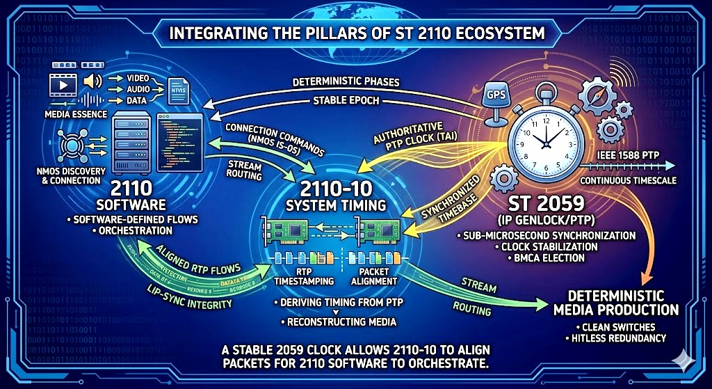
As we saw in yesterdays 2059 lession, that page and this page represent the two critical halves of building a successful IP-based broadcast facility: The Software/Orchestration Layer (from the 2110 Software page) and The Timing/Infrastructure Layer (from the 2059 page).
They relate to each other exactly like a high-performance sports car relates to a perfectly paved racetrack. One cannot function without the other. Here is how they connect conceptually and architecturally:
- The Foundation vs. The Application
2059.html (The Foundation): This page handles the physical and deterministic baseline. It ensures that every single network interface card (NIC), COTS switch, and gateway shares an identical, sub-microsecond atomic timebase (TAI). It stabilizes the hardware oscillators so that the network can mimic traditional analog genlock.
2110 Software (The Application Layer): This page is the on-ramp to the software-defined workflow. Once ST 2059 has completely stabilized the timing across the network fabric, the software layer can cleanly step in to execute essence-based routing, NMOS automated discoveries, and dynamic connection management. - RTP Timestamps Require the 2059 Clock
The software page (day 7) notes that ST 2110 breaks an SDI stream into separate video (-20), audio (-30), and metadata (-40) flows as RTP multicasts.
The Relationship: For a software receiver to merge these independent packet flows back together without lip-sync errors or video tearing, it relies entirely on the RTP timestamps embedded in the packet headers.
As yesterdays 2059.html page explains, those timestamps are mathematically derived directly from the continuous ST 2059 PTP epoch. Without the flawless 2059 clock synchronization described on your open tab, the software flows on the 2110 page would suffer from packet jitter, buffer overflows, and timing drift.
The Core Solution: IEEE 1588 PTP + SMPTE ST 2059
ST 2110 uses Precision Time Protocol (PTP) per IEEE 1588, refined by the SMPTE ST 2059 standard:
- ST 2059-2 – Defines the PTP profile optimized for professional media (domains, message rates, BMCA priorities, etc.).
- ST 2059-1 – Specifies how to derive traditional media phase (video frame boundaries, audio sample clocks, time-of-day, and LTC) from the PTP timeline.
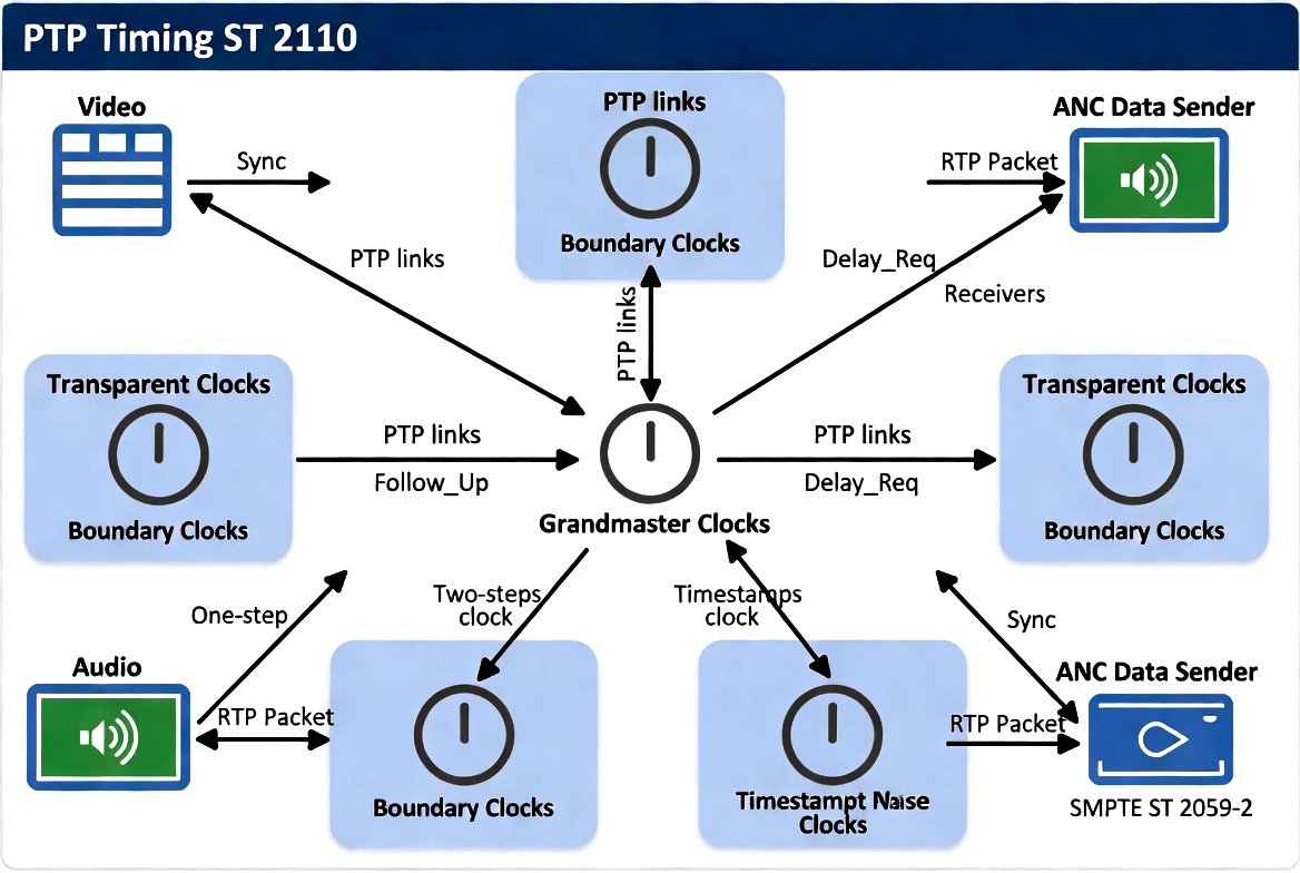
PTP distribution in a ST 2110 leaf-spine network with Grandmaster, Boundary, and Transparent Clocks
How Synchronization Works Step-by-Step
- Every device participates in PTP and locks its local hardware clock to the Grandmaster.
- Senders use this precise PTP clock to generate RTP timestamps for every media packet.
- Receivers read the incoming RTP timestamps and compare them against their own PTP-derived local clock to reconstruct the original timing.
- Because all devices share the same reference clock, independent essence flows remain phase-aligned even though they travel on separate multicast addresses.
PTP Control Loop (The Servo)
PTP is not a simple “set the clock” mechanism. It is a continuous feedback control loop (servo/PLL) that disciplines each device’s local oscillator:
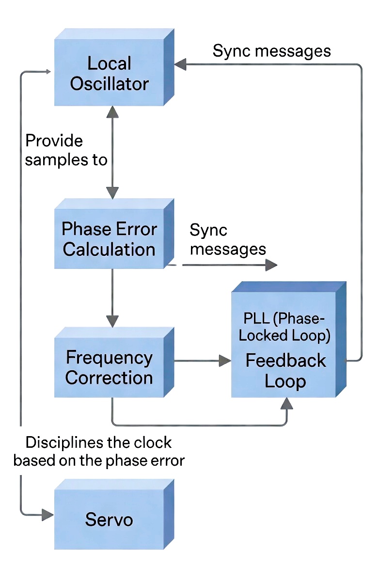
PTP servo control loop that disciplines local oscillators
Key Technical Details
- Message Rates: Sync typically runs at 8 Hz or 16 Hz. Higher rates = tighter control but more network traffic.
- One-step vs Two-step clocks: One-step inserts the exact transmit timestamp into the Sync packet on egress. Two-step sends a separate Follow_Up message.
- Transparent Clocks (TC) and Boundary Clocks (BC) in switches measure and correct for residence delay (the time a PTP packet spends inside the switch).
- Red/Blue Networks (ST 2022-7): Both paths use the same PTP domain so timing remains aligned for hitless protection switching.
Why This Is Critical
Without precise PTP synchronization you lose:
- Lip-sync between video and audio
- Glitch-free video switching and mixing
- Accurate keying and graphics overlay
- Reliable 2022-7 hitless redundancy
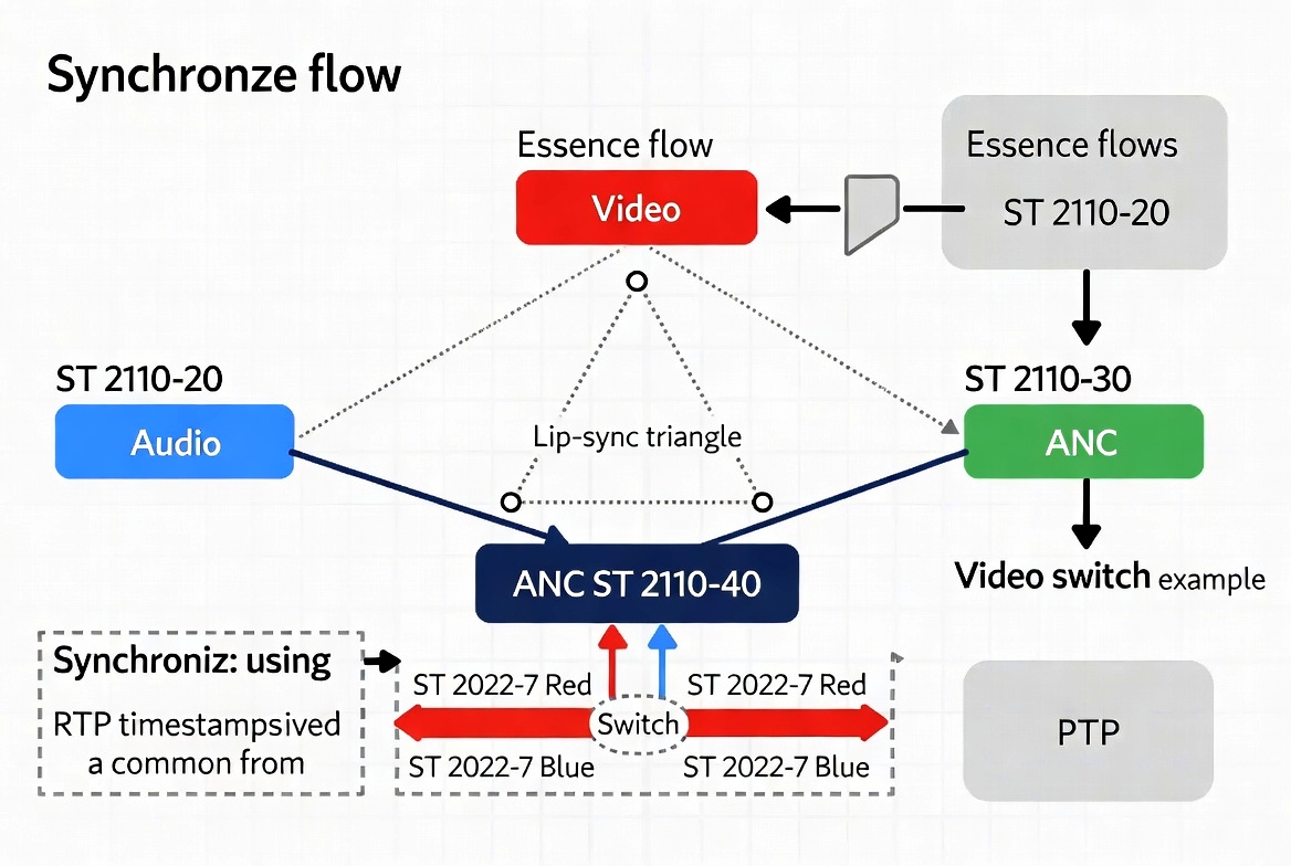
How independent Video, Audio, and ANC streams stay synchronized using shared PTP time
Bottom Line:
In ST 2110, timing is no longer carried inside the media signal. It is carried by a separate, high-precision PTP timing plane. Every RTP packet is stamped against this shared clock. That single source of truth is what allows independent video, audio, and ancillary streams to stay locked together across the entire facility — even over large IP networks.
In conclusion, what is important about this whole timing issue is Fabric Configuration vs. Software Control. The two pages mentioned from before demonstrate the division of labor between your network engineering configurations and your software control systems:
- On the 2059 page, you are managing the raw network environment: setting up Boundary Clocks, choosing E2E vs. P2P delay mechanisms, and locking down strict DSCP priority queues to ensure timing packets aren't blocked by massive media payloads.
- On the Software page, you reap the rewards of that stable environment. Because the lower layers provide disciplined timing, the software orchestration layer (like NMOS IS-04/IS-05 and SDN controllers) can safely execute clean, deterministic virtual matrix switches without relying on traditional baseband hardware patch panels.
Summary Mental Model: ST 2059 establishes the single, authoritative universal schedule across your entire IT fabric.
ST 2110 Software uses that schedule to ensure that unbundled, software-defined media streams can scale, route, and realign seamlessly from a single room to an entire campus network.