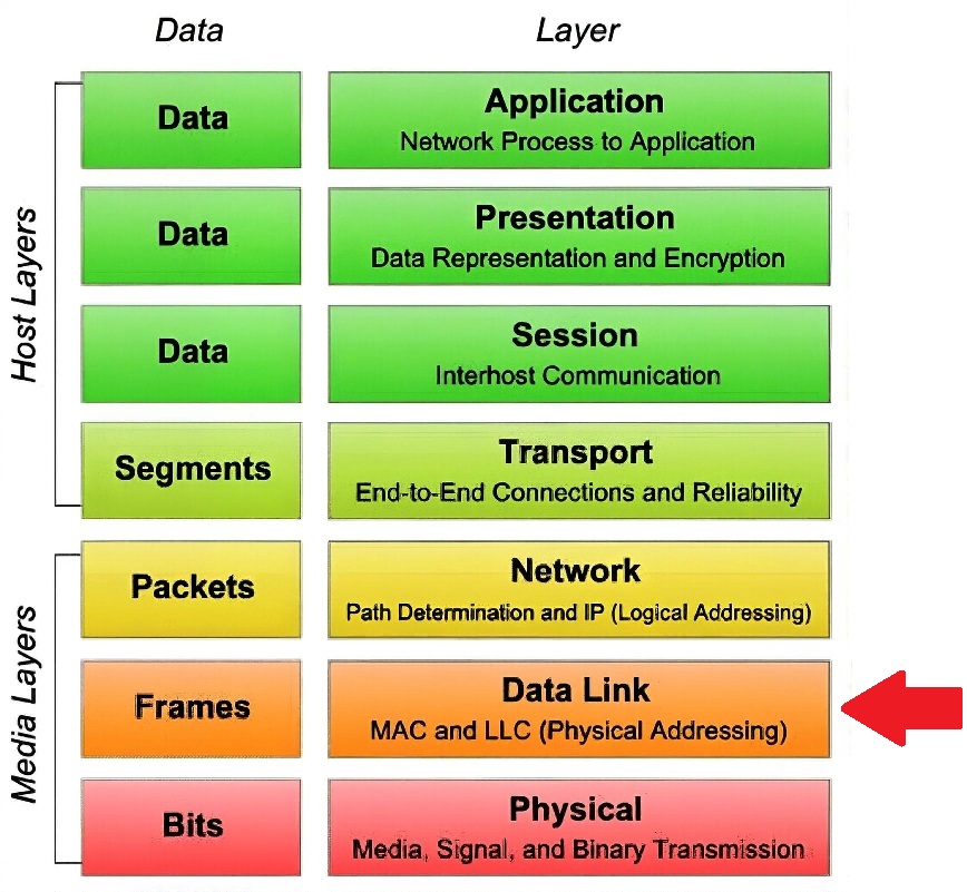
The Data Link Layer (Layer 2) provides the "local" delivery of data. While IP addresses (Layer 3) get data across the internet, MAC addresses get data across the room.
How it Works: The "Box" Analogy
Think of the Data Link Layer as the physical envelope.
The Content: Your 2110 video data.
The Address: Every Network Interface Card (NIC) has a unique, permanent MAC Address.
The Neighborhood: Data at this layer can only be sent to devices on the same local networks (VLANs) connected to the same switch. To go further, it needs a Router. Layer 2 is strictly for local delivery within the same "neighborhood" (VLAN/Subnet) and relies on Layer 3 (IP) for anything further.
Modern Switching vs. Legacy Hubs
The Old Way (Hubs): Acted like a "party line" or a ring. When one device talked, everyone else had to listen and wait. This caused "collisions" and is never used in 2110.
The Modern Way (Switches): A switch acts like a non-blocking matrix. It creates dedicated, full-speed lanes between ports. Today's switches use Full-Duplex communication that provides dedicated bandwidth to each port.
2110 Specifics: In a 2110 setup, a switch uses IGMP Snooping to act like a "smart" router. It doesn't just connect A to B; it can replicate one source (a Camera) to many destinations (Monitors, Multiviewers, and Recorders) simultaneously without slowing down the network.
The Two Sub-Layers
Media Access Control (MAC): This is the "hardware" part. It handles the physical MAC address and determines how the NIC places bits onto the fiber or copper wire.
Logical Link Control (LLC): This is the "software" interface. It acts as the bridge between the physical hardware and the Network Layer (IP). It handles flow control and identifies which protocol (usually IPv4) is hidden inside the frame.
Key Functions for 2110
Framing: Wrapping the IP packet into an Ethernet Frame.
Error Detection (CRC): A mathematical "checksum" at the end of the frame. If a single bit is flipped during a high-speed 25G video transmission, the switch or receiver will see the error and drop the corrupted frame. Corrupted packets are dropped at the hardware level to protect the integrity of the stream.
VLAN Tagging (802.1Q): This allows us to "split" one physical switch into multiple virtual ones (e.g., keeping your PTP timing traffic on a different logical path than your heavy video data).
This is all done using Ethernet Protocol. We look at that next.
 Study Plan
2110 Topo
Study Plan
2110 Topo
 Modern Switching vs. Legacy Hubs
 UPDATED
4/29/26
V260429-1.0
UPDATED
4/29/26
V260429-1.0