 Study Plan
2110 Topo
Study Plan
2110 Topo
This lesson explores the transition from hardware-based SDI to software-defined IP media routers, focusing on how professional systems achieve frame-accurate switching despite the inherent latencies of IGMP.
• How do Professional IP media routers and work?
• Building on IGMP
• Edge nodes and the Local Cluster
• Buffering
• Standards Used
• RTP
• ST 2022-7: Redundant Path Protection
• IGMP Bridge / Routing
• Layered View
To work near instaneouly they add important timing and control-layer details that make the behavior appear “instantaneous.”
 When a device (receiver) switches from one source to another — say from 239.0.0.1 (Camera 1) to 239.0.0.2 (Camera 2) — it performs two operations:
IGMP Leave for the old group (stop receiving 239.0.0.1)
IGMP Join for the new group (start receiving 239.0.0.2)
So in theory, yes — IGMP signaling can act like a “video router crosspoint,” switching between streams.
However, real-world systems layer additional mechanisms on top of IGMP to make the transition fast and seamless.
In hardware SDI routers, switching is electronic, done in microseconds. In IP multicast, the switchover involves network control and buffer synchronization.
Delays can come from:
So if you simply issue an IGMP Leave + Join, the switch/router may take up to a few hundred milliseconds to begin forwarding the new stream. That’s fine for monitoring or playout, but not fast enough for frame-accurate switching (e.g., live production cuts).
How Broadcast Systems Improve It? Professional IP video routers and control systems add control-layer intelligence to make the switch “instant”:
| Technique | Purpose |
|---|---|
| Pre-join / Pre-subscribe | The destination joins multiple multicast groups in advance but only decodes one at a time. Switching just changes which buffer is read. |
| Fast-Leave suppression | Keeps the previous stream alive until the new one is confirmed (avoids black frames). |
| Multicast control API (NMOS IS-05 / SDP) | Orchestrates stream mapping in milliseconds using centralized control, not raw IGMP. |
| Receiver-side gating | Software mutes or crossfades between streams locally, independent of IGMP timing. |
In other words, IGMP still provides the underlying plumbing, but a control layer above it makes the user experience as fast and deterministic as a baseband router. While IGMP is the "plumbing" of the network, it is insufficient on its own for live production.
Professional systems (like GV AMPP or Imagine Magellan) use a Control Layer (NMOS IS-05/SDP) to orchestrate these shifts, often using Pre-joins or Receiver-side gating to make the switch feel instantaneous.
When you click a crosspoint in an IP router:
From the operator’s perspective, it’s instant — but under the hood, there’s careful sequencing.
Modern video routers build on IGMP, adding pre-joins, orchestration, and receiver-side logic to achieve “instant” transitions.
So while every output does not pre-subscribes to every input, each output can pre-subscribe to a few sources (or use fast-join mechanisms) to make switching seamless.
So instead of hard-wired crosspoints, you have a matrix of IGMP relationships that your control system manages dynamically.
Normal Operation (One Active Stream per Output)
Each destination (receiver/output) subscribes to exactly one multicast group, the one it’s supposed to “see.”
When you press a new crosspoint:
For fast switching (say, on a production switcher or preview bus):
This reduces visible switch latency to a few frames or less.
| Output | Active Join | Pre-Join |
|---|---|---|
| Out 1 | 239.0.0.1 (on-air) | 239.0.0.2 (next) |
| Out 2 | 239.0.0.3 | 239.0.0.4 |
| Out 3 | 239.0.0.5 | — |
The system controller keeps track of these states, orchestrating Joins and Leaves only when needed.
Lets look at a real system: The Grass Valley Ampp (Agile Media Processing Platform).
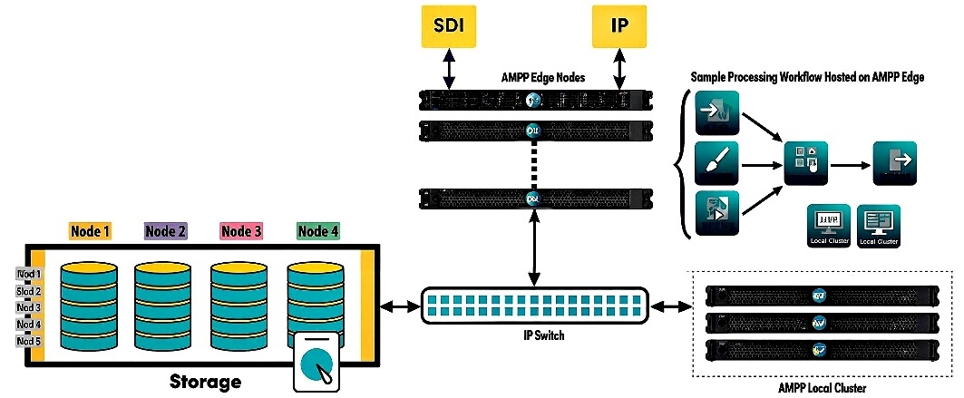
Two predominate types of equipment stand out. Edge nodes and the "Local Cluster."
Edge Node = Bridge (I/O, transport, buffering). Performs network smoothing & switching. An analogy to hark back to old technolgy: It's like an old time TV station’s “patch bay” with smart frame syncs.
The Edge Node is your hardware or software gateway that:
Think of it as the “translator and traffic controller” between your local video network and the AMPP cloud. It is considered the Gateway Layer. It is usually installed on-premises, near where media is produced or consumed:That can be an OB truck or venue, a control room, or studio facility.
Local Cluster = Processing Fabric (apps, logic, compute). The Local Cluster can also hold temporary buffers for AMPP apps (for example, frame stores, multiviewer tiles, and replay caches). It also does playout timing This is analogous to a server room or mini broadcast center.
The Local Cluster acts as a self-contained compute fabric, like your own mini version of the AMPP Cloud. Can operate autonomously if temporarily disconnected from the wider cloud. Think of the Local Cluster as the local “brain and muscles” for AMPP, running live tools and orchestrating workflows close to where the action happens. It lives on the same LAN or data center network, providing for low-latency, high-performance productions. But it can live in a private or hybrid cloud for elastic scaling.
| Concept | GV Edge Node | GV Local Cluster |
|---|---|---|
| Purpose | On-premises connection point between your local IP network (2110, SDI, NDI, etc.) and the AMPP cloud. | A group of AMPP nodes running together (on-prem or private cloud) to provide local compute, storage, and redundancy. |
| Location | Physically at your facility, OB truck, or venue. | Can be on-prem, in a private data center, or hybrid cloud. |
| Function | Handles real-time signal ingress/egress, format conversion, and buffering. | Handles distributed processing and orchestration for multiple AMPP apps in a defined environment. |
| Managed By | AMPP Orchestrator (remote control). | AMPP Fabric Manager — part of the Orchestrator that sees all nodes as a unified compute cluster. |
| Use Case | Bringing SMPTE 2110 or SDI signals into AMPP; managing local camera feeds or monitor outputs. | Running AMPP apps (e.g., Router, Multiviewer, Replay) with shared GPU/CPU resources for local operations. |
| Connectivity Role | Acts like an intelligent gateway or “bridge.” | Acts like a “mini data center” for AMPP workloads. |
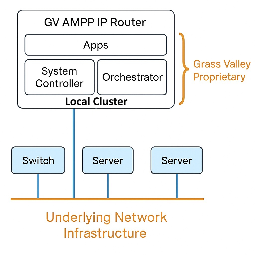
“It can be thought of as the software director in the control room. Not cutting video, but assigning who does what, when, and where.”
The GV Apps are modular, software-based production tools that plug into the AMPP ecosystem. Each app performs a traditional broadcast function — but runs as a microservice in the cloud or on an edge device.
A bit more about buffering.When we talk about “pre-join” or “buffering multiple multicast streams,” that function happens inside GV-controlled receivers such as:
Each of those receivers maintains a small circular buffer, typically:
So when you “switch” between two sources, you’re not waiting for a new IGMP Join, you’re switching which buffer’s frames you read from, locally.
Network Infrastructure (Switches / Fabric) Has No Awareness of Buffers
The IP network; your switches, routers, and spine-leaf fabric only:
It doesn’t store or delay packets intentionally.Its job is to move multicast packets quickly, deterministically, and consistently, but not to hold or align them.
Here’s what happens in a fast switch:
GV processing nodes act like specialized media switches. All outgoing media streams pass through the GV "smart switch" along the way. A “virtual matrix” built on top of the IP network fabric.
The GV output is published to a new multicast group, e.g. 239.1.1.10. Other devices subscribe via IGMP Join, just like any other multicast source. To the network, this GV endpoint simply looks like another source transmitter, but with much smarter switching logic.
The end receiver (the network endpoint that joins the GV output multicast) does not inherently know what the original source was based purely on the network packets. However, the GV control/orchestration layer does know and maintains that association through metadata (via NMOS, SDP, and routing tables). So, to the network, it’s “just another multicast stream.” But to the GV system, it’s “Camera 1 feed, switched through Router Output A.”
When the GV node outputs a new stream (say 239.1.1.10), it generates new RTP packets with its own SSRC (stream ID). Those packets don’t contain a reference to “Camera 1” or the original multicast group (239.0.0.1).
To be clear, the Network Layer (L2/L3) has no awareness of the "Source." When a stream passes through a processing node or "smart switch," it is technically a new multicast group with a new SSRC (Synchronization Source) ID.
The GV Orchestrator (or NMOS IS-05 controller) maintains a mapping table. When you switch Output A to Camera 2, the controller updates that mapping instantly. The receiver (e.g., Multiviewer) doesn’t need to know that the packets changed. The controller ensures it’s always “tuned” to the correct GV output address. So, the identity follows in the control layer, not the IP layer.
Each GV output has an SDP file (Session Description Protocol) that describes its parameters:
m=video 5004 RTP/AVP 96
c=IN IP4 239.1.1.10/32
a=source-filter: incl IN IP4 239.1.1.10 10.1.0.50
a=ssrc:12345678 cname:GVRouterOutA
This SDP may include GV-specific or NMOS-specific tags that reference the upstream source name or ID, but that’s metadata. It is not visible at the network packet level.
What the End Receiver Sees
| Layer | What It Knows | Who Maintains Identity |
|---|---|---|
| Network (L2/L3) | Only the source multicast (e.g., 239.1.1.10) | Ethernet/IP switch |
| Media (RTP/2110) | Payload timestamps, SSRC, PTP clock | GV node / RTP stream |
| Control (SDP/NMOS) | Logical signal name (Camera 1, Studio A PGM) | GV Orchestrator |
Before we leave this section, lets look at a preview of of the standards to come and how they affect our router operation.
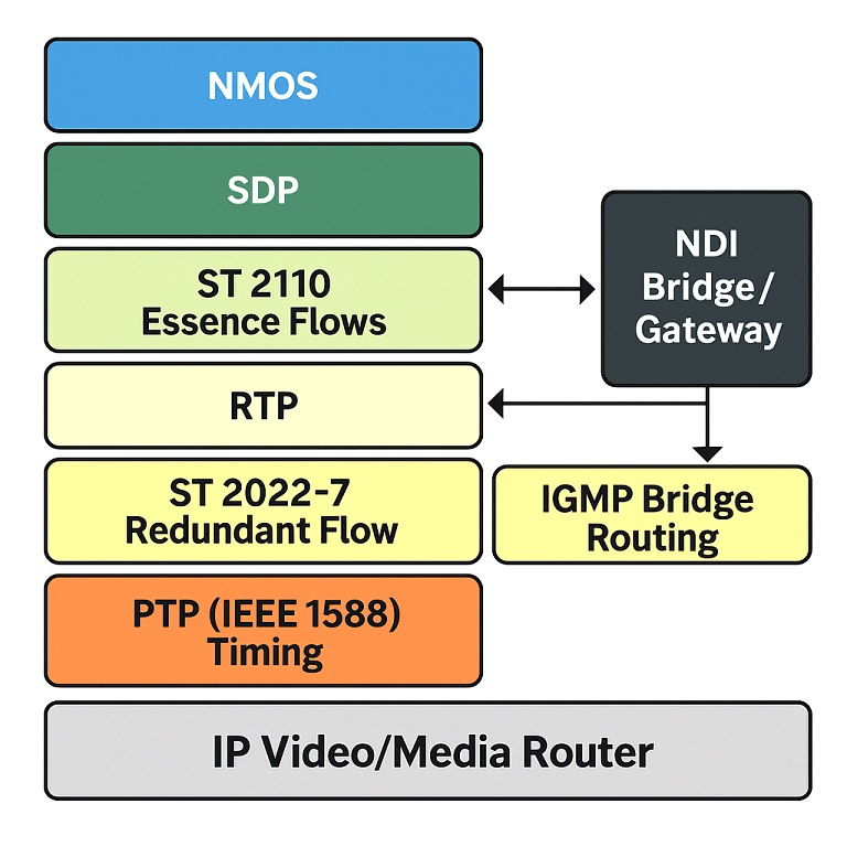
In the diagram, NMOS (Networked Media Open Specifications) and SDP (Session Description Protocol) handle the control and connection logic that makes IP media routing possible.
NMOS: specifically IS-04 and IS-05 provides automatic discovery, registration, and connection management of 2110 devices. It allows the router or controller to know what sources and destinations exist on the network and to connect them instantly without manual IP entry.
SDP files describe the technical details of each stream; its IP address, ports, codecs, and timing, so receivers know how to subscribe to and decode it.
Together, NMOS and SDP form the control layer that orchestrates media flows across the 2110 infrastructure shown in the diagram.
SMPTE ST 2110 defines how video, audio, and ancillary (metadata) signals are carried as separate, synchronized streams across an IP network.
Key Parts:
Sub-Standard & What It Carries
2110-10 Timing & synchronization (via PTP IEEE 1588-2)
2110-20 Uncompressed video (one stream per essence)
2110-30 Uncompressed PCM audio
2110-40 Ancillary data (captions, timecode, control data)
ST 2110 sits at the media plane. It’s how the content (your actual pictures and sound) travels. Each stream flows as RTP packets (Real-time Transport Protocol) wrapped in IP headers, precisely timed by PTP.
RTP:The Transport Mechanism
Purpose: The Real-time Transport Protocol carries the actual media payload (video, audio, data) over UDP.
Functionally: Adds sequence numbers and timestamps to packets so receivers can reconstruct continuous video/audio. Works at the transport layer (Layer 4). Provides no retransmission, by design. It prioritizes low latency over error correction.
Interactions:
ST 2022-7: Redundant Path Protection
Purpose: Ensures hitless switching (no black frames or glitches) if a link fails.
Functionally: Two identical RTP streams are sent over diverse network paths (“A” and “B” networks). At the receiver, packets are compared and reconstructed. Any lost packet from one path is replaced by its twin from the other. Operates below 2110, at the transport reliability layer.
Interactions:
NDI Bridge / Gateway
Purpose: NDI is a proprietary but widely used IP video standard from NewTek (now Vizrt). It doesn’t follow SMPTE 2110 framing, timing, or PTP clocking. When integrated into a 2110 router environment, NDI typically connects through a bridge or gateway; software or hardware that:
Functionally: Converts NDI streams (which use TCP/UDP and their own sync model) into 2110-compliant RTP streams with PTP alignment. Translates NDI’s internal naming into NMOS-registered sources. Allows legacy or production-level NDI devices to participate in 2110 routing.
Interactions:
IGMP Bridge / Routing
Purpose: Manages multicast group membership — the mechanism that lets receivers “subscribe” to media streams.
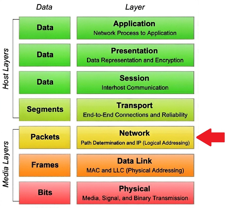
Functionally: IGMP (Internet Group Management Protocol) tells switches which ports want which multicast addresses (e.g., 239.0.0.1). Switches then only forward those packets to interested receivers, saving bandwidth. Works at the network layer (L3) inside the Media Plane.
Interactions:
Here’s the typical end-to-end chain in a 2110-based IP router:
[Source: Camera or Server]
│
▼
ST 2110 → defines the essence (video, audio, data)
│
▼
RTP → packetizes it into real-time transport streams
│
▼
ST 2022-7 → duplicates streams across two network paths for redundancy
│
▼
IGMP Routing → sends multicast streams only to subscribed receivers
│
▼
NMOS / SDP → tell devices how to discover, describe, and connect
│
▼
NDI Bridge (optional) → translates NDI sources to/from 2110
Layered View
| Layer | Role | Protocols |
|---|---|---|
| Control Plane | Discovery & connection | NMOS (IS-04/IS-05), SDP |
| Media Plane | Transport & timing | SMPTE ST 2110, RTP |
| Reliability Layer | Redundant protection | SMPTE ST 2022-7 |
| Network Layer | Multicast distribution | IGMP, PIM |
| Integration Layer | Interoperability | NDI Bridge/Gateway |
Summary: