
 Study Plan
2110 Topo
Study Plan
2110 Topo
This lesson explains how private IP addresses are used and how it fits into the SMPTE ST 2110 stack.
• What Private IP Ranges Are
• Why Broadcast Systems Use Them
• Control Networks
• Network Segmentation
• Getting Out to the World
• Sample Broadcast IP Planning Checklist
Here’s how private IP ranges are typically used in broadcast systems:
 Defined by RFC 1918 (IPv4), the private ranges are:
These are not routable on the public internet — they’re reserved for internal use within organizations.
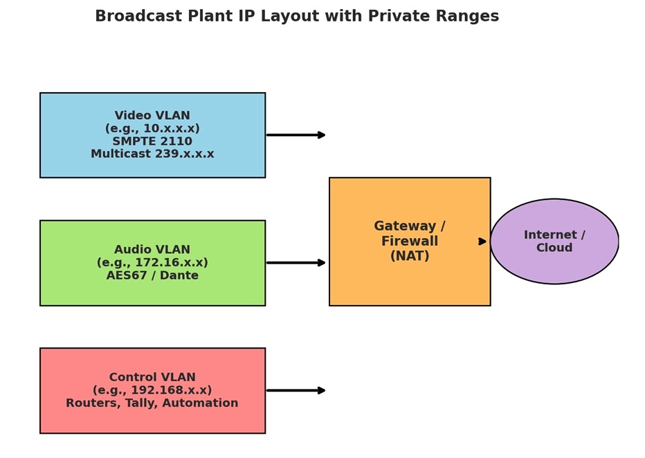
To reach the public internet (for streaming, contribution feeds, cloud services), NAT (Network Address Translation) is used at the firewall or gateway.
Broadcast systems use private IP ranges to build secure, isolated, and scalable local networks for production. They rely heavily on VLANs and multicast inside those ranges to move live media streams reliably, then use NAT/firewalls when they need to connect to the wider world.
 Explanation
 Diagram
 IP Range Calculator
| Category | Detail | IP Address
General conventions in assigning IP addresses for clarity, troubleshooting, and interoperability: Video, Audio, and Control are usually kept on separate VLANs with their own IP ranges. Example: Video VLAN → 10.1.x.x/24, Audio VLAN → 172.16.x.x/24, Control VLAN → 192.168.x.x/24 This prevents congestion and makes troubleshooting easier. Static IP addressing is strongly preferred for cameras, switchers, servers, and intercoms in 2110. Reason: deterministic routing — you always know which device is at which IP. DHCP may be used for laptops or guest monitoring but not for core devices. Devices of the same type or role are grouped in ranges for readability. Example: Cameras → 10.1.0.10 – 10.1.0.30 Replay → 10.1.0.50 – 10.1.0.60 Graphics → 10.1.0.70 – 10.1.0.80 This way, engineers can tell at a glance what type of device an IP belongs to. |
|---|---|---|
| Truck A - Video VLAN | Subnet | 10.1.0.0/24
10.1.0.0 = the network ID, not a usable host address. /24 = subnet mask 255.255.255.0. This means the first 24 bits (10.1.0) are the network portion. The last 8 bits are host addresses. 10.1.0.0 represents the entire subnet, not a single host.If you try to ping a network address (like 10.1.0.0 when it belongs to a subnet such as 10.1.0.0/24), most operating systems and routers will drop the packet because 10.1.0.0 is not a valid host. You’ll usually see: Destination host unreachable, or simply no reply. So 10.1.0.0/24 defines a block of 256 total addresses: 10.1.0.0 → network ID (not assigned to a device). 10.1.0.1 → 10.1.0.254 → usable host addresses. 10.1.0.255 → broadcast address. The /24 mask gives enough room for dozens of cameras, replay servers, encoders, and video devices, but keeps things small enough for easy management. |
| Truck A - Video VLAN | Multicast Range | 239.1.0.0/16
Multicast ranges (239.x.x.x) are chosen uniquely per truck (e.g., 239.1.x.x vs 239.2.x.x) so that multicast traffic stays separate and avoid conflicts. SMPTE 2110 uses multicast (239.x.x.x) for essence streams. Rules of thumb: Reserve a multicast block per truck/studio (e.g., 239.1.x.x for Truck A, 239.2.x.x for Truck B). Keep multicast groups aligned with source devices (e.g., Camera 1 always → 239.1.0.11). Use an IGMP querier + IGMP snooping so multicast is routed only to devices that request it. |
| Truck A - Video VLAN | Devices Assigned | Camera 1 – 10.1.0.11 Camera 2 – 10.1.0.12 Video Server – 10.1.0.50
These are from the 10.x.x.x private Class A range (very large, ideal for media networks).Using different subnets per truck avoids overlap when multiple trucks are connected. /24 gives up to 254 usable IPs, which is plenty for the video side of a single truck. |
| Truck A - Audio VLAN | Subnet | 172.16.1.0/24
These are from the 172.16.0.0 – 172.31.255.255 private range (Class B). Using /24 again gives 254 usable hosts plenty for intercom panels, microphones, Dante/AES67 devices. Keeping audio in a separate private range helps engineers troubleshoot and keep clocking (PTP) stable. |
| Truck A - Audio VLAN | Devices (AES67/Dante) | Intercom Panel 1 – 172.16.1.21 Mixer – 172.16.1.30 |
| Truck A - Control VLAN | Subnet | 192.168.1.0/24
These are from the 192.168.0.0 – 192.168.255.255 private range (common for IT/admin networks). Control gear (routers, tally, switchers, automation PCs) doesn’t need huge subnets so /24 is simple and fits nicely. This also makes it easier for engineers to quickly recognize control devices since many expect 192.168.x.x for “management.” |
| Truck A - Control VLAN | Devices (Routers, Tally, Automation) | Router Control – 192.168.1.10 Tally Server – 192.168.1.20 Switcher Panel – 192.168.1.40 |
| Truck B - Video VLAN | Subnet | 192.168.1.0/24 |
| Truck B - Video VLAN | Multicast Range | 239.2.0.0/16 |
| Truck B - Video VLAN | Devices Assigned | Camera 1 – 10.2.0.11 Camera 2 – 10.2.0.12 Replay Server – 10.2.0.60 |
| Truck B - Audio VLAN | Subnet | 172.16.2.0/24 |
| Truck B - Audio VLAN | Devices (AES67/Dante) | Intercom Panel 1 – 172.16.2.25 Mixer – 172.16.2.35 |
| Truck B - Control VLAN | Subnet | 192.168.2.0/24 |
| Truck B - Control VLAN | Devices (Routers, Tally, Automation) | Router Control – 192.168.2.10 Tally Server – 192.168.2.20 Switcher Panel – 192.168.2.40
|
| Shared Infrastructure - Switch/Router | VLAN Trunking Configured (Yes/No) | Yes |
| Shared Infrastructure - Switch/Router | Multicast Routing Enabled (Yes/No) | Yes |
| Shared Infrastructure - Switch/Router | IGMP Snooping Enabled (Yes/No) | Yes
IGMP (Internet Group Management Protocol) is the protocol hosts (like cameras or servers) use to join or leave multicast groups. Snooping means the switch “listens in” on IGMP messages as they pass through. The switch then builds a table of which ports have asked to join which multicast groups. Without IGMP Snooping: A switch doesn’t know which devices need the multicast. It will flood the multicast stream to all ports in that VLAN. This wastes bandwidth and can overwhelm devices that don’t care about the traffic. With IGMP Snooping: The switch sends multicast only to the ports that requested it (those who joined that group). This keeps network load efficient and ensures each device only sees the traffic it asked for. IGMP Snooping = selective multicast forwarding. It makes multicast behave more like unicast (point-to-point), but still scalable. Essential in broadcast facilities to prevent network congestion from high-bitrate video streams. |
| Gateway/Firewall | NAT Range for Internet Access | 10.255.0.0/16
NAT (Network Address Translation) is when a firewall or router converts private IP addresses (like 10.x.x.x or 192.168.x.x) into a public IP address so those devices can communicate on the internet. It’s like having a whole office full of phones but only one public phone number — the PBX figures out who’s calling whom. In a broadcast plant, you may have hundreds of private IP devices (cameras, servers, audio gear). None of those can directly talk to the internet because private ranges aren’t routable outside. The NAT Range is the block of private IPs that the gateway/firewall is configured to translate for internet access. Example: Inside video VLAN → 10.1.0.0/24 Inside audio VLAN → 172.16.1.0/24 Inside control VLAN → 192.168.1.0/24 NAT Range might be defined as 10.0.0.0/8 (everything inside starting with 10.) or just a subset like 10.255.0.0/16 if only certain devices need external access. These addresses get translated to one (or a pool) of public IP addresses on the firewall when they go out. Normally, video and audio flows (SMPTE 2110) stay private and don’t need NAT. But control systems, monitoring, or contribution encoders may need to talk to a remote NOC, cloud playout, or CDN. The NAT Range defines which internal devices are allowed through the firewall → so engineers can control security and bandwidth. 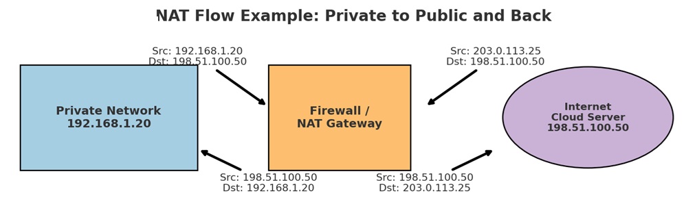
|
| Gateway/Firewall | Public IP(s) | 203.0.113.25 (example RFC 5737 test address) |
| Gateway/Firewall | Streaming/Cloud Contribution Setup (Yes/No) | Yes
In your checklist, this refers to the configuration that allows your on-premises broadcast system (like OB trucks or studios) to send live feeds into cloud services for: Live streaming (YouTube, Facebook, Twitch, etc.)or contribution to cloud playout or production (Avid, Viz Now, GV AMPP, AWS MediaConnect, etc.) Remote monitoring or backup recording. Key Elements Involved: Encoding - Raw SMPTE 2110 or SDI video/audio is too heavy to send directly to the internet. A contribution encoder (hardware or software) compresses it into transport formats like: SRT (Secure Reliable Transport), RIST (Reliable Internet Stream Transport), RTMP (older, but still used for social platforms), MPEG-TS over UDP Firewall/NAT Configuration - The encoder sits inside a private VLAN (e.g. 10.1.0.50). The Streaming/Cloud Contribution Setup defines: Which private IPs are allowed to egress. The NAT/public IP they will use. The ports/protocols opened for SRT, RIST, RTMP, etc. Cloud Destination Setup: In AWS, GCP, or another provider, you configure ingest endpoints (IP and port). Example: SRT listener at 34.120.200.10:9000. The firewall maps the local encoder → cloud endpoint. Redundancy & Monitoring Often dual encoders send the same feed via diverse ISPs for resilience. Contribution setup usually includes monitoring probes that confirm signal health (bitrate, packet loss, latency). Example in Practice - Truck A video server has IP 10.1.0.50. Encodes main program feed into SRT. Firewall allows outbound to 35.200.50.25:9000 (cloud playout). NAT translates 10.1.0.50 → 203.0.113.25. Cloud service receives the stream, decodes it, and makes it available for Master control, OTT streaming, Cloud storage |
| Truck Interconnect | No overlapping private ranges confirmed | |
| Truck Interconnect | Unique multicast groups per truck | |
| Truck Interconnect | VLAN isolation and trunking tested |