
 Study Plan
2110 Topo
Study Plan
2110 Topo
This lesson explains Switch Setup and how it fits into the SMPTE ST 2110 stack.
• Stacking vs. Core Switching
• Redundancy and Topology
• Configuration and Merging
• Multicast and IGMP
• Access Control List (ACL)
• Access Control and Security
• Link Aggregation Group (LAG) and LACP
• Switch User Authentication
 Setting up and organizing the IP Networking infrastructure in the facility is a combination of configuring the switches along with a small router, which we will look at shortly. You will often hear about a managed switch. Simple switches can simply be hooked up and they will route traffic based on MAC addresses, and not much more. A “Managed” switch will allow VLANs to be setup, security to be implemented, and much more. The trade off is that there can be extensive setup and management duties for these switches.
Up until now, we have looked at switches as separate entities. However, in a broadcast environment, they are often integrated to act as a single logical unit. Traditionally, this is achieved through a stack configuration, where multiple physical switch frames are cabled together and managed via a single IP address.
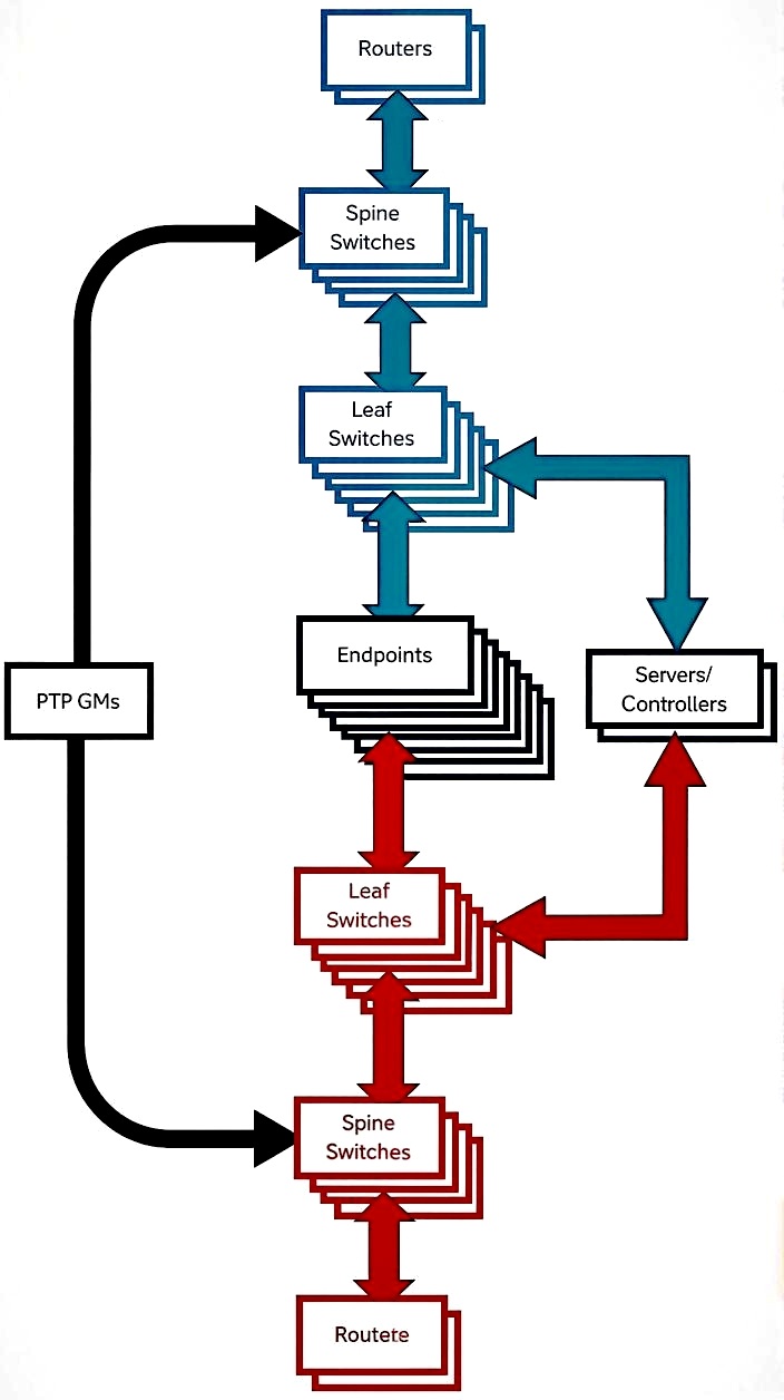
In a stack, one frame is elected as the master and another as the backup. This "super switch" (typically consisting of six to eight units) shares a common control plane. While stacking is efficient for edge devices, modern SMPTE ST 2110 deployments often move away from stacking in favor of a Spine-Leaf (Core) architecture. In a Spine-Leaf setup, "Leaf" switches connect to "Spine" (Core) switches using high-bandwidth links (like 100G). This avoids the "single point of failure" inherent in a stack's shared brain, providing the massive, non-blocking throughput required for uncompressed video.
When you set up a stack, dedicated stacking ports—usually fixed—are used to cascade traffic between frames. While a simple chain (daisy-chain) works, it is superior to connect the bottom frame back to the top to create a ring topology. This loop ensures that if a single frame fails, traffic can be redirected in the opposite direction, allowing the rest of the unit to function without interruption. For critical 2110 infrastructure, using redundant power supplies (RPS) for at least the master and backup frames is highly recommended.
The master and backup frames store all configuration files. Consequently, if a frame fails, a replacement unit can be inserted and set up automatically by the master without manual intervention. If the replacement frame has a different port density, the master will map the previous configuration to the available ports.
Stacks can be split by hardware failure or merged by extending the stack cable loop to include a second set of frames. During a merge, the masters negotiate to determine which remains the primary controller—often based on the longest uptime, the lowest stack ID, or the MAC address. Note that it is preferable to let the master assign IDs automatically; manually assigned IDs can cause a "losing" master to shut down during a conflict.
Unlike simple data networks, a switch in an IP Media environment must do more than just forward frames based on MAC addresses. To handle ST 2110 streams, the switch must be configured for IGMP Snooping. This prevents "multicast flooding" by ensuring that high-bandwidth video streams are only delivered to the specific ports that requested them, rather than overwhelming every device in the stack.
When two stacks are merged, no two frames can have the same ID. The combined configuration files are now only found in the winning master and backup frames.
Note:If a switch is inserted which is set to run as a standalone unit, it will continue to do so and the master/backup will treat that frame as a failed unit and route traffic around it.
Managed switches include specialized safeguards to mitigate the effects of Broadcast Storms. A storm occurs when broadcast or multicast traffic loops infinitely through a network, consuming all available bandwidth and crashing the control plane. To prevent this, switches use Storm Control to monitor traffic levels; if a pre-defined threshold is exceeded, the switch will block the offending traffic or shut down the port for a set period.
In an SMPTE ST 2110 environment, care must be taken when configuring these protections. Because 2110 relies on high-bandwidth multicast streams (often exceeding 1Gbps or 10Gbps per flow), an improperly configured switch may mistake legitimate video data for a broadcast storm. If the "Storm Control" threshold is set too low, the switch might "block" your video feed, thinking it is protecting the network from a loop.
To further secure the infrastructure, you can restrict traffic on individual ports using an Access Control List (ACL). This allows the switch to only permit traffic from a specific list of MAC addresses. These lists can be set up manually by the engineer, or the switch can be instructed to "learn" the connected devices and then lock the port to those specific IDs.
Additionally, managed switches allow you to define the throughput capabilities of each port. By instructing a port to advertise a specific speed or by manually capping its rate, you can prevent a single malfunctioning end-device from saturating the Switching Fabric. While older systems required manual crossover settings, modern NICs utilize Auto-MDIX to sense wiring orientation automatically, making manual "crossover" configuration largely unnecessary in contemporary IP Media setups.
Connector wiring on switch ports is generally “crossed” where receive pins are transmit pins, etc. You can set the port to treat its port like the switch it is, or like a port on an end device. This is not often necessary anymore, as most NIC cards can sense if the transmit and receive wires are crossed and act accordingly.
Managed switches allow multiple physical ports to be combined into a single logical high-bandwidth path, known as a Link Aggregation Group (LAG). This process is typically orchestrated by the Link Aggregation Control Protocol (LACP). By grouping ports, you can increase the total throughput between devices—for example, combining four 10GbE ports to create a 40GbE logical pipe.
To set up a LAG, the participant ports must be configured as a full-duplex set with matching parameters (speed, priority, and flow control). While LAGs provide a layer of redundancy, they are subject to specific architectural constraints: ports assigned to a LAG generally cannot be members of a VLAN independently, and auto-negotiation must be disabled to ensure stability.
In a 2110 environment, it is vital to distinguish between Link Aggregation and Seamless Protection Switching (ST 2110-7).
LAG Redundancy: Provides "link-level" protection. If one cable in a LAG is pulled, the switch redistributes traffic to the remaining cables. However, this often results in a momentary "hit" or dropped packets during the convergence time, which can cause a glitch in uncompressed video.
ST 2110-7 (Hitless): Rather than relying on the switch to "fix" a broken path, ST 2110-7 sends two identical, bit-for-bit copies of the essence data over two completely independent network paths (Red and Blue networks).
Because ST 2110-7 provides true "hitless" switching—where the receiver can seamlessly swap between streams if one path fails—it is the preferred method for broadcast-critical signals. LAG is more commonly reserved for trunking general data or management traffic where a few dropped packets are acceptable during a failover.
To help visualize the difference between standard network redundancy and broadcast-grade "hitless" redundancy, here is a comparison of LACP (used in LAGs) and SMPTE ST 2110-7.
| Feature | Link Aggregation (LACP) | ST 2110-7 (Seamless Protection) |
|---|---|---|
| Primary Goal | Increased Bandwidth & Link Failover | "Hitless" signal integrity |
| Method | Combines physical ports into one logical pipe. | Sends two identical streams over two separate networks. |
| Recovery Time | 50ms to 1s+ (Convergence time) | 0ms (Instantaneous) |
| Impact on Video | Visible "Glitch" or dropped frames during switchover. | No Impact. The receiver has a second copy ready to use. |
| Network Path | Usually stays within the same switch/stack. | Requires two physically isolated "Red" and "Blue" networks. |
| Best Use Case | Control data, file transfers, and Management NICs. | Live 2110 Video, Audio, and Metadata essence. |
Technical Insight: Why the Difference? The reason LACP causes a "glitch" is that the switch must detect the link failure and then re-route the traffic to a surviving port. Even with "Fast" LACP timers, this takes time. ST 2110-7 is superior for broadcast because the receiver is already looking at two identical packets; if one is missing, it simply grabs the other without needing to wait for the network to "re-learn" the path.
Managed switches provide robust methods for authenticating traffic and administrative access. A switch port facing an external or untrusted ingress point—such as an internet connection or an outside vendor feed—can be set up to require strict authentication. While internal "trusted" ports may not require credentials to pass traffic, the management interface of the switch should always be secured. The simplest method is to store user credentials in a local database residing on the switch itself.
For enterprise-level facilities, separate authentication servers are used to centralize security. The two primary protocols are RADIUS and TACACS+:
TACACS+ (Terminal Access Controller Access-Control System Plus): Developed by Cisco, TACACS+ is more robust and secure than RADIUS. Unlike RADIUS, which bundles authentication and authorization together, TACACS+ separates them, allowing for more granular user privilege management (e.g., allowing a junior tech to view settings but not change them). Crucially, TACACS+ encrypts the entire body of the packet, making it the preferred choice for high-security broadcast environments.For any port requiring authentication, the switch allows the engineer to specify handling for different traffic types—such as Telnet, SSH (Secure Shell), and HTTPS—and define which specific authentication method (Local, RADIUS, or TACACS+) should be prioritized.
To conclude the Switch User Authentication section, here is a "Bottom Line" table that ranks the three primary methods by their security level and suitability for a professional ST 2110 broadcast environment.
| Rank | Method | Security Level | Data Encryption | Best For... |
|---|---|---|---|---|
| 1 | TACACS+ | Highest | Full Packet | High-security enterprise cores; granular admin permissions. |
| 2 | RADIUS | Medium | Password Only | General network access and 802.1X port security. |
| 3 | Local Database | Low | None | Small labs, standalone switches, or emergency fallback. |
While a Local Database is the easiest to set up, it is difficult to manage across a large facility because passwords must be updated on every individual switch. RADIUS centralizes this, but its lack of full-packet encryption makes it vulnerable to "man-in-the-middle" sniffing.
For the modern IP Media facility, TACACS+ is the gold standard. It ensures that every command an engineer enters is encrypted and logged, providing the audit trail and security depth required for 24/7 broadcast operations.