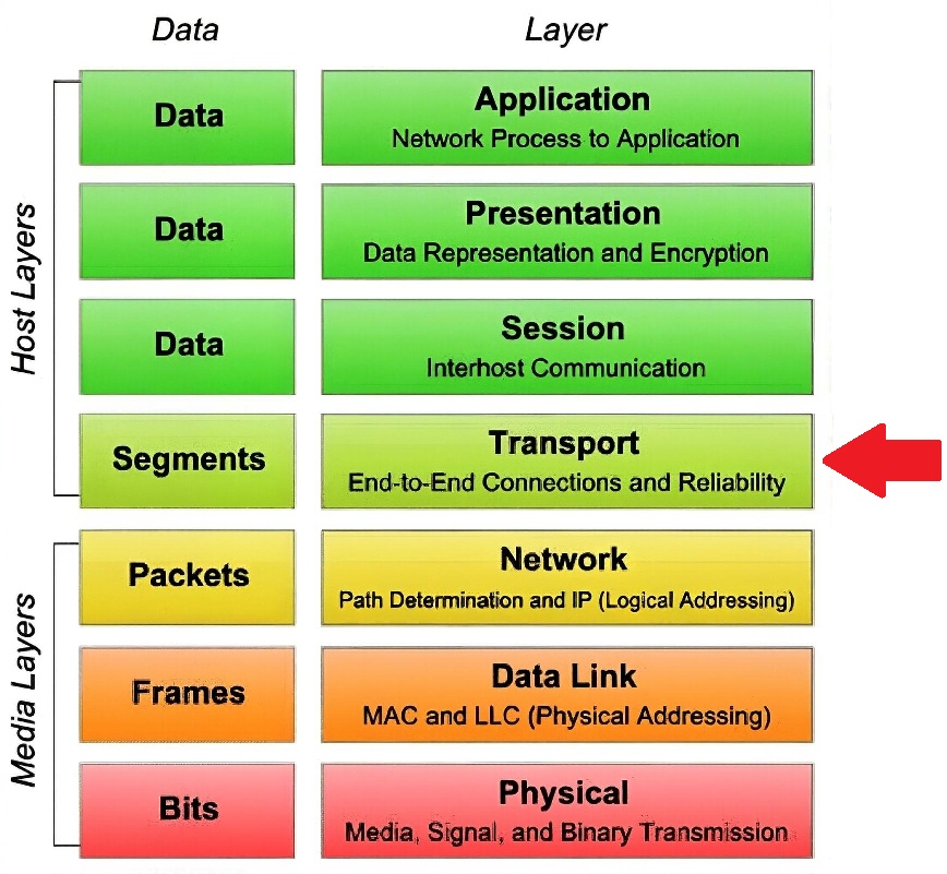
The Transport Layer (Layer 4 of the OSI model) is where network communications move from “sending packets” to “sending sessions or conversations.”
It provides the logic that lets applications on different systems exchange information reliably or in real time, depending on the use case.
The Layers Purpose
Deliver data end-to-end between two hosts.
Segment large application data into smaller packets.
Manage flow control, error detection, and session management.
Provide port numbers that identify which application gets the data.
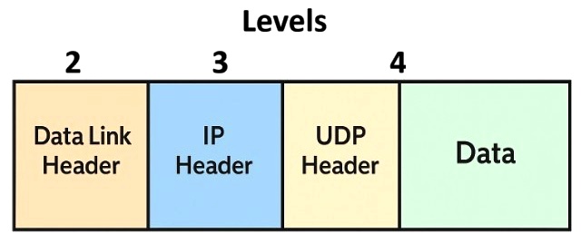
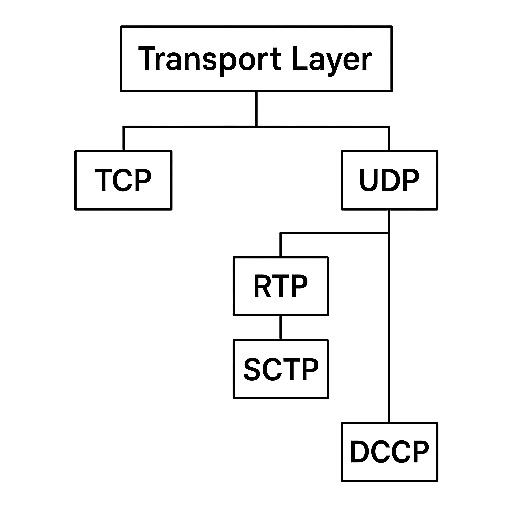
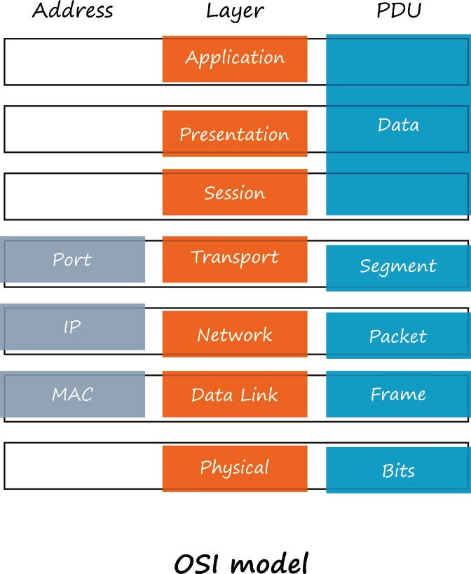
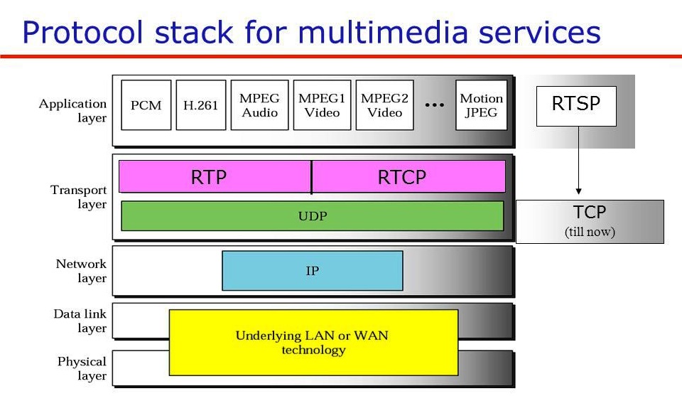
Graphics on how the Transport Layer fits into the overall stack.
RTP and Related Protocols in the OSI Model
Protocol
OSI Layer(s)
Why
RTP
Layer 5–7 (Session / Application)
Adds timestamps, sequence numbers, and payload type identification for real-time media streams
RTCP
Layer 5–7
Provides control, statistics, and feedback (jitter, packet loss, round-trip time) for RTP streams
UDP
Layer 4 (Transport)
Lightweight, connectionless packet delivery without retransmission or ordering guarantees
RTP and RTCP are not transport protocols; they rely on UDP.
OSI Layers 5–7 are often collapsed in practice, which is why RTP/RTCP are shown as spanning them.
This table cleanly reinforces why ST 2110 = RTP over UDP over IP, not “RTP is Layer 4.”
Core Transport Protocols
Protocol
Connection Model
Reliability
Ordering
Congestion Control
Typical Use
Example Applications
TCP (Transmission Control Protocol)
Connection-oriented
Yes
Yes
Yes
Reliable file or data transfer
HTTP, FTP, SMTP, SSH
UDP (User Datagram Protocol)
Connectionless
No
No
No
Real-time, low latency
RTP, VoIP, live video, DNS, games
SCTP (Stream Control Transmission Protocol)
Hybrid (message-oriented)
Yes
Yes (multi-streaming without HOL blocking)
Yes
Telecom signaling, multi-homing
SS7 over IP, Diameter
DCCP (Datagram Congestion Control Protocol)
Connection-oriented (datagram)
Partial (with congestion control)
No
Yes
UDP-like with built-in congestion control
Experimental streaming/gaming
RTP is not a Layer-4 transport protocol, even though many people loosely talk about it that way.
How They Relate
UDP and TCP are the primary transport protocols defined in IP networking.
RTP, SCTP, and DCCP are transport-layer extensions that sit on top of UDP or IP, depending on the use case.
RTP relies on UDP for its lightweight delivery but adds sequencing and timing information for media synchronization.
Control and signaling (like RTCP, SIP, RTSP) run alongside or above them to coordinate sessions.
Application Type
Stack
Description
Web Page
HTTP → TCP → IP
Reliable, ordered transfer of data
File Transfer
FTP → TCP → IP
Accuracy more important than latency
Live Video
RTP → UDP → IP
Timeliness more important than accuracy
Audio Call
SIP → RTP → UDP → IP
Session management plus real-time media
Control Plane
RTSP or RTCP → UDP / TCP → IP
Controls start, stop, and synchronization of streams
Why Video Uses UDP (Not TCP)
UDP is fast and lightweight, and it is connectionless. No handshake, no retransmission, no congestion window. Packets are just sent. The receiver either gets them or doesn’t. So it has Low overhead, and latency.
Perfect for real-time media like: Live video (SMPTE 2110, SRT, RTP), voice (VoIP), games or live telemetry. TCP tries too hard to be “perfect,” as it guarantees reliability and order. Lost packets are retransmitted. Packets are delivered in order. TCP uses a congestion window that throttles speed when loss occurs.
That’s great for files and web pages, but a disaster for live streams. Retransmitting a lost video frame after 300 ms is pointless, the event has already moved on. When TCP detects loss, it slows down, causing freezes or buffering. The result: jerky playback, increased latency, buffering “spikes.” UDP simply discards lost packets and moves on, so your stream stays smooth even if you lose some packets.
UDP lets the application manage timing. Video applications (e.g., RTP or MPEG-TS over UDP) add their own timing logic:
Timestamps in RTP or PCRs in MPEG-TS maintain playback order.
FEC (Forward Error Correction) or redundant paths (SMPTE 2022-7) handle loss proactively.
Jitter buffers absorb small variations in packet arrival.
This gives designers control over latency and quality, instead of TCP’s “one-size-fits-all” recovery. Multicast (one sender/many receivers) is only supported with UDP. TCP is strictly one-to-one (unicast).
Broadcasters can use
IGMP joins to deliver the same live feed efficiently to hundreds of endpoints. Example: 239.1.1.1:5000 - one UDP stream received by multiple decoders.
TCP
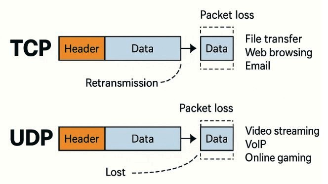
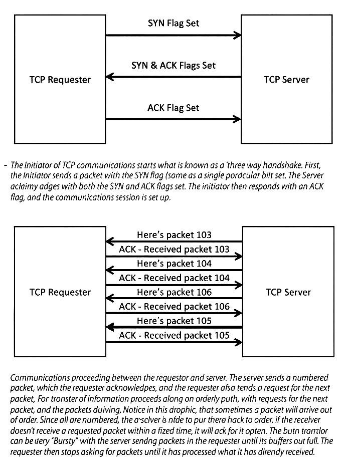
TCP (Transmission Control Protocol) is a connection-oriented transport-layer (OSI Layer 4) protocol that provides reliable, ordered, and error-checked delivery of data between two endpoints. It establishes a session using a handshake, segments data into numbered packets, retransmits lost data, controls flow so a fast sender doesn’t overwhelm a slow receiver, and applies congestion control to adapt to network conditions. TCP is used where correctness matters more than latency, such as web traffic, file transfers, and email.
UDP in detail
Connectionless, best-effort. No handshake, no retransmit, no built-in ordering or congestion control.
Great for real-time media where timeliness beats perfection (live video/audio, 2110/RTP, MPEG-TS).
Reliability/timing are achieved by the application layer (RTP timestamps, FEC, redundancy) and the network (QoS, multicast).
UDP is connectionless and uses IP destination addressing to determine how packets are delivered. The key difference lies in unicast vs. multicast addressing, with multicast having two main models: Any-Source Multicast (ASM) and Source-Specific Multicast (SSM).
1. Unicast Addressing
Destination format: Single specific IP address + port
Example: 203.0.113.10:5000
Behavior: One-to-one delivery. The packet is sent directly to one receiver.
Routing: Uses standard unicast routing tables (longest prefix match).
UDP port role: The destination port identifies the specific application/socket on the target host (e.g., 5000 might be a custom streaming or VoIP app).
Common uses: Most client-server UDP applications (DNS queries to 8.8.8.8:53, syslog, SNMP, etc.).
2. Multicast Addressing
Destination format: Multicast group IP address + port
Example: 239.1.2.3:5000
Behavior: One-to-many or many-to-many delivery. A single packet is sent once by the source; the network duplicates it only where needed to reach group members.
Receiver/application must know source IP in advance
IGMP version
Works with IGMPv1/v2 (and v3 in INCLUDE/EXCLUDE)
Requires IGMPv3 (INCLUDE mode with source list)
Routing protocol
PIM-SM (with RP), PIM-DM, etc.
PIM-SSM (subset of PIM-SM) — no RP needed
Security / control
Less secure: any source can send to group (risk of rogue sources, DoS)
More secure: only authorized source(s) allowed; prevents unauthorized injection
Typical use
Legacy multicast apps, many-to-many (e.g., old conferencing)
Modern one-to-many: IPTV, live streaming, financial data feeds, software updates
Advantages
Flexible (multiple sources possible)
Cleaner, scalable, no RP/MSDP needed, better security
Disadvantages
Complex (needs Rendezvous Point, MSDP for inter-domain), potential abuse
Receiver must know source IP (often learned via out-of-band signaling like SDP/HTTP)
Summary of UDP multicast destination handling:
Unicast UDP → dst = one IP:port → direct delivery
Multicast UDP → dst = group IP:port → network replicates based on group membership
ASM → anyone can send → (*, G) join → traditional but less secure
SSM → only known source(s) → (S, G) join via IGMPv3 → preferred for most new deployments
In practice, modern UDP-based multicast applications (e.g., video streaming, market data) strongly favor SSM over ASM for reliability, security, and simpler network operation. More on these in Day 4
UDP Transport Framing – Detailed Explanation (Focus on Video/Streaming Use Cases)
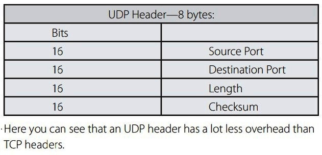
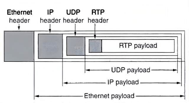
UDP provides minimal framing itself — it's just a simple datagram header (8 bytes) with source/destination ports, length, and checksum. For real-time media (especially video/audio contribution, distribution, or broadcast), additional framing layers are added on top of UDP to handle payload structure, timing, synchronization, and error resilience.
1. Common Framing Types over UDP
Raw UDP — Pure UDP payload (no extra protocol headers).
Used for simple, low-overhead custom streaming or legacy apps. Payload can be anything (e.g., raw video frames, proprietary formats). No built-in timing or sequencing.
RTP/UDP (Real-time Transport Protocol over UDP) — Most common for modern real-time media.
RTP adds a 12-byte header (sequence number, timestamp, SSRC, payload type, etc.) + optional extensions/CSRC.
Provides sequencing (detect loss/reordering), timestamps (for playout synchronization), and payload type identification.
Widely used in VoIP, WebRTC, SMPTE ST 2110, and many streaming protocols.
MPEG-TS/UDP (MPEG Transport Stream directly over UDP) — Traditional broadcast/contrib format.
MPEG-TS packets (188 bytes each, sync byte 0x47) are packed into UDP payloads.
No RTP header — relies on TS continuity counters, PCR (Program Clock Reference) for timing, and adaptation fields for timing info.
2. MPEG-TS over UDP: Packetization Best Practice
Standard practice: Pack 7 × 188-byte TS packets per UDP datagram → 1316-byte payload.
Why 7?
Ethernet MTU is typically 1500 bytes (common default).
Result: Predictable ~1316-byte UDP packets → avoids IP fragmentation, reduces jitter from reassembly, and is decoder-friendly (many hardware decoders expect this alignment).
Tools like FFmpeg often default to or recommend pkt_size=1316 for MPEG-TS/UDP outputs.
3. SMPTE ST 2110 Specifics (Professional Media over IP)
Uses RTP over UDP (not raw TS).
ST 2110-20: uncompressed video essence
ST 2110-30: audio (often AES67-compatible)
ST 2110-40: ancillary data
Precise packet pacing and RTP timestamps are critical for low-latency, genlocked playout.
Sender models (defined in ST 2110-21 – Traffic Shaping and Delivery Timing):
Narrow (N): Hardware-based, very precise timing (e.g., constant or gapped during VBI).
Narrow Linear (NL): Constant bit rate, steady packet intervals (no gaps).
Wide (W): Software-based, more flexible timing tolerances (higher jitter allowed).
Pacing ensures packets leave the sender evenly spaced → prevents microbursts that overflow switch buffers.
4. Bitrate & Pacing
Target: Constant Bit Rate (CBR) for predictability (e.g., 3 Gbps for uncompressed 1080p60, or 20 Mbps for compressed).
Packets per second calculated from bitrate ÷ packet size (e.g., 20 Mbps → ~1900 packets/sec for ~1316-byte payloads).
Pacing/shaping: Sender spaces packets evenly (e.g., every ~526 µs for 1900 pps) using hardware timers or software scheduling.
Prevents bursts → avoids tail-drop in shallow switch buffers.
In ST 2110, pacing follows ST 2110-21 models: Narrow senders are tightest; receivers declare buffer requirements via SDP.
5. Protection Options (Error Resilience over UDP)
FEC (Forward Error Correction):
Pro-MPEG COP#3 / SMPTE 2022-1 (2D parity FEC).
Organizes media packets into an L × D matrix (columns × rows).
Alarms: High FEC recovery, excessive jitter, buffer overruns/underruns.
In professional video contrib/distribution (e.g., live sports, studio-to-transmitter links), combining RTP framing, precise pacing, FEC/2022-7 protection, QoS marking, and careful buffering turns "best-effort" UDP into highly reliable, low-latency transport over IP networks.
UDP Stream Flow
In the context of real-time UDP-based streaming (e.g., video contribution, broadcast distribution, or professional media workflows like SMPTE ST 2110), the end-to-end flow involves encoding, network transport, and decoding with careful handling of timing, reliability, and quality of service (QoS). Below, we'll expand on each step, focusing on key mechanisms for low-latency, resilient delivery over IP networks.
1. Encoder Side: UDP Profile Application and Packetization
The encoder (e.g., hardware like Evertz, Imagine Communications, or software like FFmpeg/VLC) uses a configured "UDP profile" — essentially a template defining stream parameters — to prepare the media for UDP transport. This ensures consistency, interoperability, and optimization for the network.
Packetization:
The encoder breaks the media essence (video, audio, ancillary data) into UDP payloads.
RTP/UDP: Adds an RTP header (12+ bytes) for sequencing, timestamps, and synchronization. Common in modern setups like ST 2110 or WebRTC. Payload might be uncompressed video (e.g., 2110-20) or compressed (e.g., H.264/AVC, HEVC).
MPEG-TS/UDP: Packs MPEG-2 Transport Stream packets (188 bytes each) directly into UDP. Standard is 7 TS packets per UDP datagram (1316 bytes) to fit under 1500-byte MTU (after IP/UDP headers ~28 bytes). This avoids fragmentation and ensures efficient decoder handling.
Why? UDP itself lacks structure, so RTP or TS provides framing for media synchronization and error detection.
Pacing/Shaping:
The encoder schedules packet transmission at a steady rate to match the target bitrate (e.g., CBR at 20 Mbps).
Intervals: Calculated as 1 / (bitrate / (payload size * 8)) → e.g., ~1900 packets/sec for 20 Mbps with 1316-byte payloads, spaced ~526 µs apart.
Tools: Hardware encoders use FPGA/ASIC for precise timing; software uses OS timers or libraries like libavformat. This prevents "microbursts" (packet clumps) that could overwhelm network buffers.
Marks IP headers with Differentiated Services Code Point (DSCP) for QoS prioritization (e.g., EF=46 for critical audio, AF41 for video). More details in point 2 below.
Protection Application (FEC or 2022-7):
FEC: If enabled (e.g., SMPTE 2022-1), the encoder generates parity packets in an L×D matrix (e.g., 10×20: 10 columns for burst loss, 20 rows for random loss). Overhead: ~10–20% extra bandwidth, sent as separate UDP streams (e.g., main on port 5000, FEC on 5002).
SMPTE 2022-7: Duplicates the entire stream over two paths (e.g., "red" and "blue" networks), each with identical RTP/UDP packets but different source IPs or VLANs for path diversity.
Configuration Tips: Profiles often include multicast group IP:port (e.g., 239.1.2.3:5000), TTL (e.g., 32), and source-specific multicast (SSM) if using IGMPv3.
2. Network Transport: Carrying the UDP Stream
The network (LAN/WAN) forwards UDP packets from encoder to receivers. Since UDP is best-effort, QoS and multicast optimizations are crucial to minimize loss, jitter, and latency.
Switches and Routers Handling:
DSCP Honoring (QoS in Depth):
Switches/routers inspect the DSCP field in IP headers and apply policies like Weighted Fair Queuing (WFQ), Class-Based Queuing (CBQ), or Priority Queuing (PQ).
EF (Expedited Forwarding, DSCP 46): Treated as highest priority (e.g., for audio or PTP timing) — minimal queuing delay, often <1 ms per hop.
AF (Assured Forwarding, e.g., AF41=34, AF42=36): Video classes with drop precedence (e.g., AF41 low-drop, AF42 medium-drop) — ensures bandwidth allocation during congestion (e.g., 80% of link for video).
Configuration: On Cisco/Juniper switches, use ACLs or policy-maps to classify/mark/queue based on DSCP. Example: Video marked AF41 gets a dedicated queue with 50% bandwidth guarantee.
L2 Equivalent: If VLAN-tagged (802.1Q), map DSCP to CoS (Class of Service, 0–7) for priority at Ethernet level (e.g., CoS 5 for EF).
Benefits: Prevents UDP drops in mixed traffic environments (e.g., office LAN with video contrib). Without it, UDP competes equally with bulk TCP traffic, leading to jitter/loss.
IGMP Snooping for Multicast:
Switches listen to IGMP Joins/Leaves from receivers and only forward multicast UDP to ports with interested hosts (pruning unnecessary traffic).
Without snooping: Multicast floods all ports like broadcast → wastes bandwidth, risks overload.
Querier Role: If no multicast router, a switch acts as IGMP Querier to poll group membership periodically (e.g., every 60s). Supports IGMPv2 (basic) or v3 (SSM for source filtering).
Router Forwarding and QoS:
Uses PIM (Protocol Independent Multicast) for routing: PIM-SM for ASM (with Rendezvous Point), PIM-SSM for SSM (source-specific, no RP).
QoS Extensions: MPLS or SD-WAN overlays can enforce per-flow QoS across WANs, shaping traffic to avoid congestion. TTL decrements per hop to scope the stream (e.g., TTL=1 for subnet-only).
Potential Issues: Jitter from variable queuing; loss from buffer overflows. Monitor with tools like Wireshark or network probes.
3. Receiver/IRD Side: Joining, Processing, and Decoding
The receiver (Integrated Receiver Decoder or software like VLC/GStreamer) processes incoming UDP packets to reconstruct and render the media stream with minimal artifacts.
Joining the Stream (for Multicast):
Sends IGMP Join to the group IP (e.g., via socket API: setsockopt(IP_ADD_MEMBERSHIP)).
For SSM: Specifies source IP (S,G) join with IGMPv3.
Unicast: Simply binds to the UDP port and receives directly.
De-Jittering and Buffering:
Jitter buffer (50–250 ms) absorbs arrival variations: Holds packets, reorders via RTP sequence, and plays out at steady rate using timestamps/PCR.
Adaptive: Dynamically resizes based on measured jitter (e.g., smaller for LAN, larger for WAN).
Sequence/PCR Checks:
RTP Sequence Numbers: Detect gaps (loss) or reordering.
PCR (Program Clock Reference in MPEG-TS): Verifies timing accuracy (jitter <500 ns ideal for broadcast); alarms if drift exceeds thresholds (e.g., ±30 ms).
Triggers: If gaps, request retransmission (if ARQ enabled, rare in UDP) or conceal errors (e.g., frame repeat).
Applying Protection (FEC or 2022-7):
FEC Recovery: Buffers matrix blocks, uses parity to reconstruct lost packets (e.g., up to 20% loss recoverable in 10×20).
2022-7 Merge: Aligns dual streams by RTP timestamps/sequences, selects best packet per slot (e.g., from red if blue lost). Achieves "hitless" protection if paths are diverse.
Decoding and Rendering:
Extracts payload (de-mux TS or RTP), decodes codecs (e.g., SDI output for video), synchronizes audio/video/ancillary via timestamps.
Output: To monitors, switchers, or further processing. Latency: End-to-end <100 ms typical for contrib if optimized.
This flow ensures UDP, despite being unreliable, supports broadcast-grade streaming when layered with RTP/TS, QoS, and protection. For deeper dives (e.g., specific configs or troubleshooting), let me know!
Practical Defaults for UDP-Based Media Streaming (MPEG-TS/UDP and RTP/UDP in Professional Environments)
These are commonly recommended starting configurations for reliable, low-latency video/audio contribution and distribution over IP networks (e.g., broadcast, live events, studio links). They balance performance, compatibility, overhead, and resilience based on industry practices (SMPTE, Pro-MPEG, DVB guidelines, and vendor defaults).
1. MPEG-TS over UDP
This is a traditional, widely supported format for compressed video streams (e.g., MPEG-2, H.264/AVC in TS).
Payload Size: 7 × 188-byte TS packets = 1316 bytes per UDP datagram.
This is the near-universal default (seen in FFmpeg, VLC, hardware encoders like Harmonic/Evertz, and DVB specs).
Why? Fits under standard 1500-byte Ethernet MTU after IP (20 bytes) + UDP (8 bytes) headers (total overhead ~28 bytes → 1500 - 28 = 1472 available; 1316 leaves safe margin, avoids fragmentation). 8 packets would exceed and risk issues. Use pkt_size=1316 in FFmpeg or equivalent.
Encoder Buffer: 20–50 ms.
Small jitter buffer at sender to smooth output pacing without adding much end-to-end latency. Larger (e.g., 100 ms+) only if very bursty source or unstable clock.
DSCP Marking: AF41 (Decimal 34, Assured Forwarding class 4, low drop precedence).
Common for video in mixed networks — provides priority over best-effort traffic but below voice/PTP. Some setups use CS4 (32) or AF42 for medium drop. Configure switches/routers to queue AF41 traffic with guaranteed bandwidth (e.g., 40–60% during congestion).
TTL (Time to Live): 64.
Standard for WAN/regional distribution (allows ~63 hops). Use lower (e.g., 1–32) for local/LAN to limit scope and prevent leakage. Multicast TTL=1 confines to subnet.
2. RTP/UDP (e.g., SMPTE ST 2110)
Modern standard for uncompressed or lightly compressed essence (video, audio, ancillary) in professional IP production.
Pacing / Traffic Shaping: Compliant with ST 2110-21 sender models.
Narrow (N) or Narrow Linear (NL): Hardware senders — very precise, constant/gapped intervals (minimal jitter).
Wide (W): Software/flexible — higher tolerance.
Use hardware timestamps/PTP for sub-microsecond accuracy. Receivers declare buffer needs in SDP.
DSCP Recommendations:
Video (ST 2110-20): AF41 (34) or sometimes CS5 (40).
Audio (ST 2110-30 / AES67): EF (46, Expedited Forwarding) — highest priority for low jitter.
PTP (IEEE 1588 timing, ST 2059): EF (46) — critical for sync; often queued above audio/video to minimize delay variation.
This hierarchy (PTP > Audio > Video) is widely recommended in SMPTE/AES67 deployments.
2022-7 (Seamless/Hitless Switching): Enable if dual redundant paths available (e.g., separate switches/ISPs, "red/blue" networks).
Send identical RTP streams over diverse routes (different IPs/VLANs). Receiver merges using RTP sequence/timestamps. Practical defaults: Max skew 10–50 ms (Class A/B), up to 450 ms for long-haul (Class C). Use for mission-critical (no visible glitches on path failure).
3. Multicast Defaults
Prefer SSM (Source-Specific Multicast): Use 232.0.0.0/8 range (e.g., 232.1.2.3).
More secure/scalable: Receivers join specific (S,G) — only authorized source sends. Avoids rogue sources/DoS. ASM (239/8, any-source) is legacy; migrate to SSM where possible.
IGMP Version: IGMPv3 mandatory on receivers for SSM (supports INCLUDE mode with source list).
Enable on all host interfaces (e.g., Linux/Windows socket options, encoder/decoder settings).
Switch/Network: Enable IGMP Snooping (prunes traffic to interested ports only).
Configure an IGMP Querier on the VLAN if no multicast router (e.g., L3 switch acts as querier; query interval ~60–125s). This prevents flooding and ensures group membership tracking.
4. FEC (Forward Error Correction) Defaults
Use SMPTE ST 2022-1 (based on Pro-MPEG COP#3) 2D row/column parity FEC.
Matrix Size: Start modest — e.g., 8×4 or 10×5 (10–20% overhead).
Common practical: 10×10 (10% overhead, corrects up to 10-packet bursts/random loss) or 20×5 (20% overhead, better burst protection up to 20 packets).
Increase to 20×10 or larger on noisy WANs (higher overhead but more recovery). Disable on pristine LANs (loss <0.01%) to save bandwidth — FEC always adds constant overhead.
Overhead & Placement: Row + column parity sent as separate UDP streams (e.g., main port 5000, FEC ports 5002/5004). Test recovery on real links.
5. NAT/Firewall Considerations
Unicast: Pin source and destination ports statically (e.g., fixed UDP 5000–5010 range).
Open firewall rules bidirectionally for those ports/IPs. Use consistent source ports for easier ACLs. Avoid dynamic/ephemeral ports unless NAT supports UDP hole-punching.
Multicast: Typically stays inside domains/LANs (no NAT traversal needed).
Use TTL scoping (low values) and IGMP snooping to contain. For WAN multicast, rare — prefer unicast or SSM with careful routing.
These defaults provide a solid, interoperable baseline for most setups. Adjust based on link quality (LAN vs. WAN), bitrate (compressed vs. uncompressed), and redundancy needs. Always test with tools like Wireshark, Evertz MAGNUM, or vendor monitors for packet loss, jitter, and PCR accuracy. Let me know if you want configs for specific hardware (e.g., FFmpeg commands, Cisco QoS examples)!
Human readable UDP Profile
Name: PLAYOUT-HD-01
Mode: RTP over UDP (2110-20)
Dest: 232.10.20.30:50000 (SSM, Source=198.18.1.10)
DSCP: AF41 (video), EF for PTP on separate VLAN
Pacing: 2110-21 Narrow Sender, 1080i/59.94
Redundancy: SMPTE 2022-7 (Path A & Path B)
FEC: Off (LAN)
TTL: 32
Notes: Receiver jitter buffer 120 ms; IGMPv3 join (S,G); switch snooping enabled
UDP vs TCP
Feature
UDP
TCP
Connection
Connectionless
Connection-oriented
Reliability
None – best effort
Guaranteed – retransmits lost packets
Ordering
None
Ensures correct order
Overhead
Very low (8-byte header)
Higher (20–60 byte header, handshake, ACKs)
Latency
Very low
Variable / higher
Multicast Support
Yes
No
Use Case
Live video/voice, gaming, real-time telemetry
File transfer, web, email, data sync
Reaction to Packet Loss
Ignores, continues
Retransmits, slows down
Error Recovery
Handled by application (e.g., FEC)
Built into the protocol
Example Protocols
RTP, MPEG-TS, ST 2110, SRT, RIST
HTTP, FTP, SSH, Telnet
UDP trades reliability for timeliness.
TCP trades timeliness for reliability.
For live video, timeliness wins — you’d rather drop a few packets than freeze the screen waiting for them.
Ports
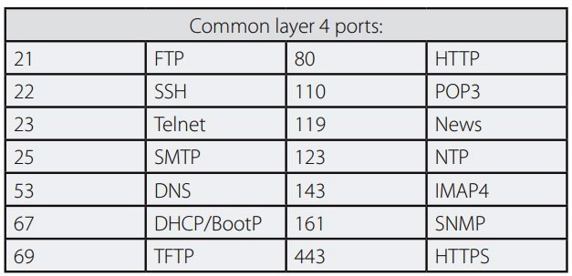
In networking, ports are 16-bit numbers (0–65535) that act like apartment numbers in a large building (the IP address is the building address). They allow a single device (identified by its IP address) to run many different network services and applications at the same time.
Key Points
Range: 0 – 65535
0–1023 → Well-Known / System ports (assigned by IANA, require root/admin privileges to bind)
Examples: 80 (HTTP), 443 (HTTPS), 22 (SSH), 53 (DNS), 25 (SMTP)
1024–49151 → Registered ports (assigned to specific applications/services)
49152–65535 → Dynamic / Private / Ephemeral ports (automatically assigned by the OS for client-side connections)
Web (HTTP/HTTPS), email (SMTP/IMAP), file transfer (FTP), SSH
Uses source port + destination port to identify unique connections
UDP
Connectionless
Unreliable (best-effort, no guaranteed delivery or order)
DNS queries, video streaming, VoIP, gaming, DHCP, NTP
Faster, lower overhead; no handshake or retransmission
How they work together:
A connection is uniquely identified by a
4-tuple
The 4-tuple (canonical definition)
(Source IP address, Source Port number, Destination IP address, Destination Port number)
Example:
(192.168.10.25, 53144, 10.10.20.50, 443)
That single 4-tuple uniquely identifies one TCP or UDP flow on a network.
Why the 4-tuple matters How operating systems demultiplex traffic
When packets arrive, the OS uses the 4-tuple to decide:
Which socket the packet belongs to
Which process should receive the data
Without the 4-tuple, multiple applications using the same destination port (e.g., port 80 or 443) could not be distinguished Multiple sessions to the same server
A single client can open many simultaneous connections to the same server and port:
Client IP Src Port Server IP Dst Port
-----------------------------------------------------
192.168.1.10 51001 93.184.216.34 443
192.168.1.10 51002 93.184.216.34 443
192.168.1.10 51003 93.184.216.34 443
Each is a different 4-tuple, hence a different session.
4-tuple vs 5-tuple (important distinction)
In many networking tools, you’ll hear 5-tuple:
(Source IP, Source Port, Destination IP, Destination Port, Protocol)
Example: (192.168.1.10, 51001, 93.184.216.34, 443, TCP)
:
Source IP : Source Port ↔ Destination IP : Destination Port
Example:
Your browser (ephemeral port 54321) → web server (port 443)
full identifier: 192.168.1.100:54321 ↔ 93.184.216.34:443
Common analogy:
IP address = street address of an apartment building
Port number = apartment number inside the building
TCP = doorman who makes sure packages arrive correctly and in order
UDP = throwing packages over the fence (fast, but some might get lost)
In short: Ports multiplex many conversations over a single IP address, and TCP vs UDP determines whether the communication is reliable & ordered (TCP) or fast & lightweight (UDP).

 Study Plan
2110 Topo
Study Plan
2110 Topo
 Why Video Uses UDP (Not TCP)