Hitting the On-Ramp to SMPTE ST 2110: From Network Plumbing to Software-Defined Broadcast
The Move to IP: Understanding ST 2110 Essence, Timing, and Orchestration
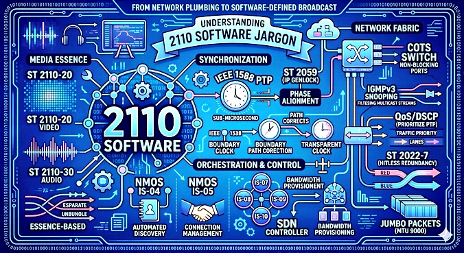
We're now at the on-ramp to SMPTE ST 2110, now that the network plumbing is in place. ST 2110 is an essence-based media system over IP: instead of one SDI “pipe,” it sends separate, time-aligned flows—video (ST 2110-20), audio (ST 2110-30/31), and ancillary data (ST 2110-40)—as RTP multicast over your Ethernet fabric.
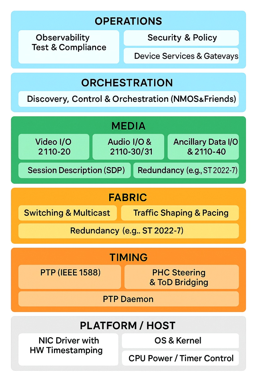
In the stack we are now at the Media level
Devices maintain perfect phase because PTP per ST 2059 replaces house sync; RTP timestamps are derived from that common clock, so switching, keying, and lip-sync remain deterministic without frame-syncing everything. Routing is no longer a fixed crosspoint. Receivers subscribe to the multicasts you publish, typically via NMOS IS-04/IS-05 (discovery + connection management) instead of patch panels. Reliability comes from ST 2022-7 seamless protection switching (dual “Red/Blue” networks), plus QoS/DSCP and PTP-aware switches (Boundary/Transparent Clocks) to control jitter and residence delay. Session details ride in SDP; control, tally, events, and audio mapping use NMOS IS-07/08/09/10 as needed.
Practically: if your lower layers provide multicast, QoS, and disciplined PTP, ST 2110 lets you scale from a room to a campus—mixing COTS servers, gateways, cameras, multiviewers, and cloud—while keeping the broadcast timing guarantees you had in SDI, now as software-defined flows.
A good way to become familar with the pieces that make up 2110 is to walk through the installation and setup process.
Items to address in selecting and choosing hardware and software when setting up your 2110 system
To set up an ST 2110 system, hardware must support IEEE 1588 PTP (ST 2059-2) using Boundary or Transparent clocks and strict QoS (CS6/EF) to eliminate packet jitter. The control plane requires IGMPv3 snooping, querier functions, and PIM-SSM to prune and route high-bitrate media streams at scale. Finally, the network fabric must be non-blocking with an MTU of 9000+, using cut-through switching and deep buffers sized for UHD bursts to prevent dropped packets.
Switch model/OS
Must-haves (hard requirements)
PTP (ST 2059)
SMPTE ST-2059 is the broadcast industry’s timing standard that turns IEEE-1588 PTP into a true “IP genlock.” It comes in two parts: ST-2059-2 defines the PTP profile and behaviors (domains, message intervals, BMCA priorities) so all gear in a facility locks to the same precise time, while ST-2059-1 specifies how to derive traditional media phases—video frame/line boundaries, audio sample ticks, and timecode—from that clock. Using TAI/UTC-aware time with PTP-capable switches (Boundary/Transparent Clocks), it delivers sub-microsecond alignment so 2110 senders/receivers stamp RTP packets against a common epoch. The result is deterministic switching, clean keying, and stable lip-sync across an all-IP plant—without distributing black burst or tri-level over coax.
one-step/two-step support
A slave needs the master’s exact send time of a Sync to compute offset and path delay. That exact time isn’t known until the frame actually leaves the NIC (hardware timestamp).
One-step clock: The Sync message itself carries the final, precise timestamp (and accumulated correctionField) when it hits the wire. Requires hardware that can edit the packet on egress (insert the real timestamp and updated correctionField “in flight”).
Pros: Fewer messages, lower processing, simpler on receivers.
Cons: Needs capable silicon in Grandmaster/BC/TC and sometimes special switch features.
Two-step clock: The Sync is sent without the final timestamp. Immediately after hardware captures the true send time, the master sends a Follow_Up message carrying that timestamp (and updated correction).
Pros: Works on hardware that can’t rewrite packets on egress.
Cons: Extra message; receivers must match Sync ↔ Follow_Up by sequence ID.
One-step embeds the truth in a single packet; two-step sends the truth right after. Pick the mode your GM/BC/TC/NIC all support reliably—and keep it uniform across your timing island.
Low, deterministic residence delay; stable under load;
per-port PTP enable
Per-port PTP enable means the switch/NIC lets you turn PTP processing on or off for each individual interface (and sometimes for each VLAN on that interface). Only ports with PTP enabled will timestamp/forward PTP messages, participate in BMCA, add TC residence delay, or act as BC masters/slaves on that segment. Ports without it behave like ordinary Ethernet—PTP packets are ignored or just forwarded as data (depending on mode).
QoS that prioritizes PTP (
CS6/EF
CS6 and EF are QoS markings from the IP DSCP (Differentiated Services Code Point) space:
CS6 (Class Selector 6) → DSCP 48 (binary 110000). Traditionally reserved for network-control traffic (routing, timing). In many 2110 plants, PTP is marked CS6 to give it the absolute highest priority.
EF (Expedited Forwarding) → DSCP 46 (binary 101110, RFC 3246). Designed for low-loss, low-latency, low-jitter traffic (classic example: VoIP). Some shops use EF for critical, latency-sensitive media/control flows—but usually 2110 essence gets CS5/AF41 and PTP stays above them at CS6.
Common QoS Markings for 2110
Traffic
DSCP
Decimal
802.1p CoS (typical)
PTP (timing)
CS6
48
6
Voice / “expedited”
EF
46
5
2110 video/audio
CS5 / AF41
40 / 34
5 / 4
Control/management
CS3 / CS2
24 / 16
3 / 2
Rule of thumb for 2110: mark PTP = CS6 (strict highest); mark media = CS5/AF41; keep control below that. Then map DSCP to strict-priority/LLQ queues in your switches so PTP can’t be delayed.
querier, fast leave
IGMP Querier = the device that periodically asks “who’s interested in which multicast groups?” so the switch/router can keep pruning/maintaining multicast forwarding state.
Fast Leave = when a host says “I’m done with this group,” the switch immediately stops forwarding that group on that port without sending extra checks—reduces drain time/join-latency.
, source filtering (
SSM 232/8
SSM 232/8 refers to Source-Specific Multicast using the IPv4 group address block 232.0.0.0/8 (i.e., 232.0.0.0–232.255.255.255). In SSM (per RFC 4607), receivers join multicast as (S,G)—they specify both the Source (S) unicast address and the Group (G) in 232/8—so the network builds a tree directly to that source. Benefits: no Rendezvous Point, simpler control plane, less risk of unwanted sources, and predictable behavior (great for ST 2110).
Quick notes:
Edge must use IGMPv3 (for (S,G) joins).
Routers run PIM-SSM; typical config sets the SSM range: ip pim ssm range 232.0.0.0/8.
Example group: G = 232.1.2.3, with a sender S = 10.110.0.10 → receivers join (10.110.0.10, 232.1.2.3).
For IPv6, SSM uses FF3x::/32 (not 232/8).
)
If routing multicast:
PIM-SSM
PIM-SSM (Protocol Independent Multicast – Source-Specific Multicast) is the L3 multicast routing mode where receivers join a stream from a specific source S to a group G—written (S,G)—instead of “any source.” Routers build a direct tree to that source (no Rendezvous Point), using the unicast routing table for RPF checks. Benefits: simpler control plane, faster/safer joins, no unwanted senders (great for 2110). Requirements: IGMPv3 at the edge for (S,G) joins, PIM-SSM on the routed links, and an SSM group range (commonly 232.0.0.0/8 in IPv4).
, solid RPF behavior, (*,G)/(S,G) scale
Group/entry capacity sized for your 2110 flows (thousands+ typical)
Hitless media transport
MTU 9000 (or 9216) end-to-end
MTU 9000 (a.k.a. “jumbo frames”) means the IP payload on an interface can be up to ~9,000 bytes instead of the default 1,500. 9216 is a common switch max frame size that leaves headroom for Ethernet/VLAN/MPLS overhead so a 9,000-byte IP MTU won’t get dropped.
Why use it
Lower overhead: fewer packets → less per-packet header/interrupt/CPU cost.
Higher throughput headroom: helpful for 2110-20 UHD streams or 2022-7 dual paths.
Smoother pacing: senders can hit line rate with fewer packets.
Gotchas (important)
End-to-end match required: every hop (NICs, switch ports, LAGs, firewalls) must support the same MTU or you’ll see drops/black-holes/frag.
PTP stays small: keep PTP at standard/mini frames with highest QoS (e.g., CS6). Use jumbo only for media flows.
Latency & QoS: big packets can block high-priority traffic if QoS/strict-priority isn’t configured (2110-21 pacing + proper queues).
Tooling/mix issues: tunnels, VLAN stacks, or SPAN ports may need >9000 (hence 9216) to avoid truncation.
Quick rules of thumb
Set media interfaces to MTU 9000 (on hosts) and switches to 9216 max frame (or vendor equivalent).
Verify with ping -f -l 8972 (Windows) or ping -M do -s 8972 (Linux) to test end-to-end (adds ICMP/IP headers ≈ 28 bytes).
Keep PTP/NMOS/control in small-frame classes; ensure QoS prioritizes them above jumbo media.
Clean support for
ST 2022-7
SMPTE ST 2022-7 (Seamless Protection Switching, “hitless”)
It sends two identical RTP streams (legs A and B) over separate network paths. The receiver aligns by RTP sequence/timestamp and merges them, picking the first good packet it sees—so packet loss, jitter, or even a path failure is invisible on output.
Where it’s used: With ST 2110 essences (video-20, audio-30, ANC-40) and other RTP media to keep live signals on-air during link/switch faults.
What you need:
Two independent networks/NICs (separate failure domains).
PTP-aligned senders so packets match across legs.
A receiver buffer sized for differential delay between A and B (adds a little latency).
Pros: “Hitless” fault masking, no retransmits, simple at endpoints.
Tradeoffs: 2× bandwidth, careful QoS on both paths, and correct buffer tuning (too small → slips, too big → added delay).
Rule of thumb: Use 2022-7 for critical program paths; pair with 2110-21 pacing and strict QoS so PTP/control stay priority over jumbo media.
(independent Red/Blue VLANs/VRFs, equal features on both)
Performance / buffers
Non-blocking fabric, predictable latency; buffers sized for 2110 UHD bursts without drops
Cut-through or low-latency store-and-forward; per-queue shaping/policing
Cut-through switching: The switch starts transmitting a frame as soon as it reads the destination MAC (and often VLAN/CoS)—before the full frame is received.
Pro: Ultra-low latency (tens of nanoseconds to a few µs).
Con: Can forward errored frames (CRC not yet known), and is more sensitive to congestion because it can’t absorb microbursts with deep buffering.
Store-and-forward: The switch buffers the entire frame, verifies CRC, then forwards.
Pro: Cleans bad frames, better with speed mismatches and microbursts.
Con: Adds one frame time of latency (e.g., ~12 µs for a 1500-B frame at 1 GbE; ~1–2 µs at 10/25 GbE; proportionally higher for jumbo).
Low-latency store-and-forward: Architectures and pipelines that keep store-and-forward but minimize per-hop delay (tight buffers, fast lookups).
Per-queue shaping / policing (QoS)
Switch ports maintain multiple hardware queues (e.g., Strict Priority for PTP, then Expedited Forwarding for media, then best-effort, etc.).
Shaping (egress): Smooths traffic to a target rate (CIR/PIR) by queueing and releasing packets at a controlled pace (token bucket). Use: Prevent bursts from overrunning downstream links; keep 2110-21 pacing tidy. Policing (ingress or egress): Enforces a cap—excess packets are dropped or remarked immediately. Use: Protects the fabric from misbehaving senders; keeps PTP/control safe from jumbo floods.
Why this matters for ST 2110. Latency: Cut-through (or very low-latency store-and-forward) keeps hop delay tiny, helping tight PTP and RTP timing.
Determinism: Per-queue shaping ensures media flows exit at predictable rates; policers stop a single device from clobbering the network.
Design tip: Put PTP in a strict-priority, non-shaped queue; put video/audio in high-priority shaped queues; keep best-effort/control in lower queues. If congestion is possible or you mix speeds, store-and-forward with good QoS is usually safer than pure cut-through.
Ops & lifecycle
LTS/“gold star” software train; ISSU/GR
Pick the stable (gold-star) LTS image (Long-Term Support release stream: fewer new features, hardened & supported longer) and use ISSU/GR-style maintenance (In-Service Software Upgrade: upgrade switch OS without dropping data-plane packets (hitless or near-hitless)) with proper PTP redundancy—so upgrades feel invisible on air.
or planned maintenance that won’t kill PTP
Streaming telemetry
(gNMI/JSON), sFlow/NetFlow
Streaming telemetry (gNMI/JSON): Switches/routers push live metrics (interfaces, queues, PTP stats, ACL hits) to a collector via gNMI using JSON (or GPB). Low-latency, high-resolution, vendor-neutral; perfect for dashboards and alerts in a 2110 plant (think offsets, drops, queue depth every 1–2s).
For 2110 you want to see PTP class, media classes, and best-effort separately.
Sane PTP show tooling: Human-readable commands/pages that expose: domain, GM identity, state (MASTER/SLAVE), stepsRemoved, offsetFromMaster, meanPathDelay, announce/ sync intervals, and TC/BC status—ideally with history/graphs.
Why it matters for 2110: Lets you prove timing health and QoS (PTP stable, media not dropping), catch multicast/QoS misconfig, and correlate faults (e.g., queue spikes → RTP gaps).
Rule of thumb: collect gNMI for time-series, add sFlow/NetFlow to see flows, and always enable per-queue counters + readable PTP “show” outputs.
JT-NM
JT-NM = Joint Task Force on Networked Media — a coalition led by EBU, AMWA, SMPTE, and VSF to accelerate IP-based professional media.
Sets common architectures & practices for live/media-over-IP (how discovery, control, timing, and transport fit together).
Bridges standards and specs: aligns SMPTE ST 2110 (transport/timing) with AMWA NMOS (IS-04/05, etc.) and operational guidance.
Publishes key guidance like TR-1001-1 (how 2110/NMOS devices should behave on engineered networks).
Runs the “JT-NM Tested” program (at NAB/IBC): vendors get interoperability badges for 2110/NMOS features so buyers know what plays well together.
Think of JT-NM as the umbrella coordination that turns individual standards into a working, interoperable ecosystem.
Tested history preferred
Security
RBAC/TACACS+/RADIUS, SSH, mTLS/PKI
RBAC — Role-Based Access Control: authorize actions based on a user’s role (operator vs admin).
TACACS+ — Terminal Access Controller Access-Control System Plus: AAA protocol for device logins/commands (common on switches).
RADIUS — Remote Authentication Dial-In User Service: AAA protocol typically for network access (802.1X, Wi-Fi, VPN).
SSH — Secure Shell: encrypted remote CLI/management session to devices/servers.
mTLS — mutual Transport Layer Security: TLS where both client and server present certificates (two-way auth).
PKI — Public Key Infrastructure: the certificate/CA system that issues, validates, and revokes keys/certs used by TLS/mTLS.
baseline; 802.1X if you need port security
ACLs/micro-segmentation; MACsec (if mandated)
ACLs / micro-segmentation; MACsec (if mandated) — in a 2110 plant this line is about containment and (optionally) encryption on the wire.
ACLs (Access Control Lists) & micro-segmentation
What: Narrow “who can talk to whom” using L2/L3/L4 rules,
(IP/port/protocol), per-VLAN/VRF/port. Micro-segmentation = applying those rules granularly (per device, role, or flow), not just at the perimeter.
Why: Shrinks blast radius, blocks stray/unwanted traffic (rogue senders, bad joins), protects control/PTP from media floods.
How for 2110: Permit only SSM multicast groups/ports needed; deny the rest.
Whitelist PTP (IPv4 224.0.1.129 UDP/319/320 or IPv6 equiv) and keep it strict priority.
Limit NMOS/SDP/management to controllers + endpoints (SSH/HTTPS/API only).
Enforce per-port ingress ACLs with counters; log minimally to avoid CPU hits.
Use VRFs/VLANs (or group-based tags/SGT) to separate media, PTP, control, and out-of-band mgmt.
MACsec (802.1AE) — “if mandated”
What: Link-layer encryption between switches/NICs; protects frames against snooping/tamper on each hop. Keys via MKA/802.1X.
Why optional: Adds operational overhead (keying, hardware support) and a little latency/MTU overhead; many facilities rely on physical security + segmentation instead.
Use when: Compliance or customer policy requires encryption on the wire (studio to core, truck to dock, rented dark fiber). Ensure hardware offload, adjust MTU (~+32B), and confirm PTP still meets timing budgets.
Rule of thumb:
Start with good segmentation (VLAN/VRF + tight ACLs at ingress) and prove with counters/telemetry; add MACsec only where policy or risk demands encryption, verifying timing (PTP) and throughput remain within spec.
Nice-to-haves (strongly recommended)
Your hardware should support NMOS IS-04 and IS-05 to automate device discovery and connection management without manual configuration files. The switch infrastructure should include an uncompressed-aware orchestration or SDN controller to handle dynamic multicast bandwidth routing and prevent oversubscription. Finally, the system needs centralized telemetry and monitoring software with packet-capture capabilities to ensure full visibility into your media streams.
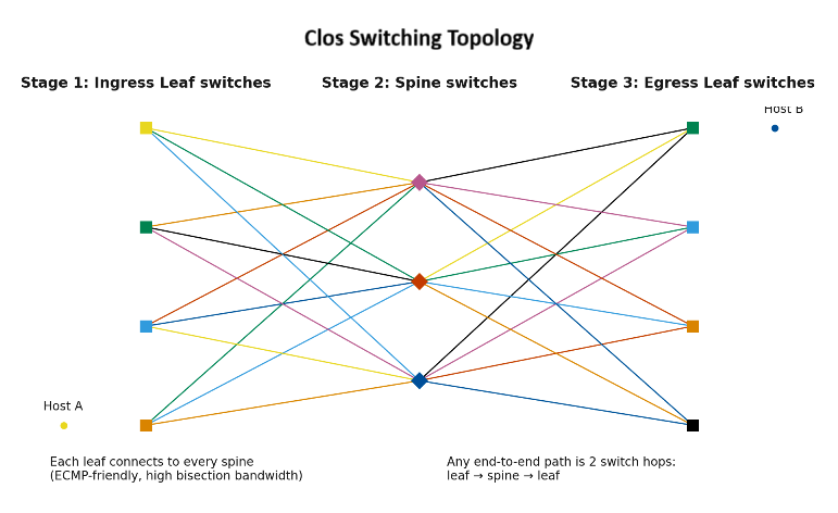
Spine-leaf (Clos) aware ECMP with deterministic pathing;
Spine-leaf (Clos) aware ECMP with deterministic pathing = a data-center style fabric and routing approach that gives predictable, balanced paths for your media flows.
Spine-leaf (Clos): Endpoints connect to leaf switches; leaves connect to all spines. No east-west bottlenecks, uniform hop count, easy scale-out.
ECMP (Equal-Cost Multi-Path): The fabric can use multiple equal-cost routes at once. A per-flow hash (5-tuple, VLAN, etc.) picks one path, so no packet reordering.
Deterministic pathing: The hash/seed and topology are controlled so the same flow always takes the same path, and when a link fails, resilient hashing moves only the affected flows (minimal churn/jitter).
Why it matters for 2110: Stable latency/jitter per flow; no reordering for RTP. Balanced load across spines without surprises. Lets you purposely separate 2022-7 A/B legs onto different ECMP paths/spines (independent failure domains). Keep PTP on strict-priority queues; ECMP is per-flow, not per-packet.
Clos (pronounced “cloh”) refers to a multistage switching topology invented by Charles Clos (1952). Instead of one giant switch, you build a large, scalable, often non-blocking fabric from many small switches arranged in stages:
Ingress (leaf) → Middle (spine) → Egress (leaf) — classic 3-stage Clos
Larger fabrics use 5-stage (leaf–spine–core–spine–leaf)
Key benefits: high bisection bandwidth, predictable latency, fault tolerance, and easy scale-out. Modern “spine-leaf” data-center networks are practical IP implementations of a Clos fabric; with ECMP hashing, each flow takes one equal-cost path without reordering—great for RTP/2110 media.
VRF separation
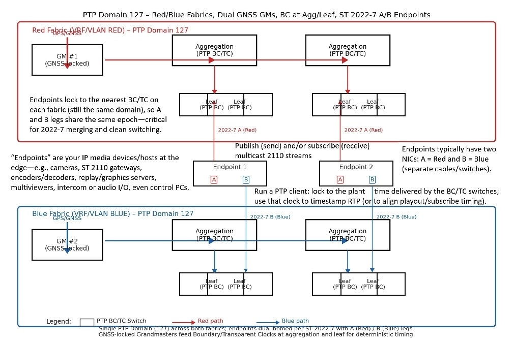
VRF separation for Red/Blue = put your two ST 2022-7 networks (“Red” and “Blue”) into different VRFs (Virtual Routing & Forwarding instances) so they behave like two independent routers/fabrics on the same switches.
Why do it? Hard isolation. Each VRF has its own routing table, ARP/ND, IGMP/PIM state, QoS stats. No accidental traffic “leak” between legs. Duplicate addressing allowed. You can reuse the same subnets in Red and Blue without conflict (handy for simple host configs). Independent control planes. Each VRF has its own IGMP querier, and if you route multicast, its own PIM-SSM domain. Cleaner ops/telemetry. Per-VRF counters and joins make troubleshooting A/B legs trivial.
How it maps to 2110 / 2022-7: Endpoints have two NICs (or 2 ports): one in VRF-Red, one in VRF-Blue. Each leg carries the same RTP flow to a different (S,G) path; the receiver does the hitless merge. PTP: same domain on both legs, but timing packets live in each VRF separately. Keep PTP strict-priority in both. Multicast: run IGMPv3 snooping + querier per VRF; if you must route, enable PIM-SSM per VRF and set SSM ranges in each.
Practical tips: Symmetry: Mirror VLANs, QoS, ACLs, and MTU on both VRFs. Red ≡ Blue (policy parity). Gateways: If you do L3 at the leaf, use anycast gateway per VRF so hosts have a local default GW on each leg. No cross-talk: Don’t leak routes between VRF-Red and VRF-Blue. If an exception is required, use an explicit firewall/route-leak with ACLs. ECMP/paths: Keep independent uplinks/spines per VRF; aim for disjoint physical paths where possible. Testing: Verify join/prune tables and (S,G) counts in each VRF; pull a link on Red and confirm Blue stays hitless.
for Red/Blue
Anycast-Gateway support
Anycast-Gateway support (often called distributed default gateway) lets every leaf switch present the same gateway IP/MAC to hosts in a VLAN/VRF. Hosts always use a local first hop—even if they move to a different rack/leaf—so routing is fast, symmetric, and resilient.
How it works: Each leaf is configured with the same SVI IP (e.g., 10.110.10.1/24) and a shared virtual MAC for that VLAN/VRF. Hosts ARP for the gateway; the local leaf answers with the virtual MAC. Inter-VLAN/VRF traffic is routed on the local leaf; if the destination is elsewhere, the leaf uses ECMP to a spine. If a leaf or uplink fails, hosts on other leaves still see the same gateway—no HSRP/VRRP failover events or ARP churn.
Why it’s great in a 2110 fabric: Low, predictable latency: first hop is always local; no hairpin to a “pair” or core. Mobility: move a sender/receiver to another leaf—same gateway, zero re-IP. Scale + resilience: no active/standby FHRP; every leaf is active. Fits Red/Blue: do Anycast GW per VRF (VRF-Red, VRF-Blue) for clean 2022-7 separation.
Design notes / gotchas: Use a consistent virtual MAC and identical SVI IPs on all leaves for that VLAN/VRF. Keep policy parity (ACL/QoS/MTU/DSCP maps) on every leaf; otherwise behavior differs by rack. If you run L3 at the edge, pair with spine-leaf ECMP; consider EVPN (or equivalent) to advertise MAC/IP reachability cleanly. PTP/2110: Anycast GW doesn’t change L2 behavior for PTP; still give PTP strict priority and keep Red/Blue in separate VRFs/VLANs. Watch ARP/ND scale; enable ARP suppression/EVPN proxy where supported to reduce noise. Testing: from a host, ping the gateway; move the host to another leaf and confirm same gateway IP/MAC, same reachability; pull a leaf uplink—traffic should reroute via ECMP without host changes.
Rule of thumb: In spine-leaf plants, use Anycast gateways on every leaf (per VRF) for first-hop routing that’s local, fast, and failure-tolerant—ideal for deterministic ST 2110 media networks.
eAPI/REST/NETCONF/gNMI
eAPI / REST / NETCONF / gNMI — ways to program/network-automate switches/routers.
eAPI (e.g., Arista eAPI): Vendor’s HTTP/JSON RPC to run CLI-like commands and get structured JSON back. Easy for scripts; vendor-specific.
REST (REST/RESTCONF): HTTP verbs (GET/POST/PUT/DELETE) on URLs representing config/state. With RESTCONF, models are usually YANG. Widely supported; human-friendly.
NETCONF: XML-over-SSH protocol using YANG models for transactional config (candidate/commit/rollback) and state retrieval. Vendor-neutral, reliable for big changes.
gNMI: gRPC (binary) with protobuf + YANG-derived paths; great for streaming telemetry (subscribes at 1–2s or faster) and can also set/get config/state. High performance, modern.
Rules of thumb:
Quick scripts / vendor features → eAPI/REST.
Model-driven, transactional config → NETCONF.
High-rate telemetry + modern APIs → gNMI (plus gNMI set where supported).
;
Ansible collections
Ansible collections are the way Ansible packages and distributes automation content. They’re namespaced bundles that can include:
Modules (the task actions), roles, plugins (lookup, filter, connection), playbooks, and docs/tests
Versioned and released to Ansible Galaxy or private registries
Installed as a unit and referenced by name, e.g. arista.eos, cisco.ios, junipernetworks.junos, ansible.utils
Why they matter (esp. for network/2110)
Give you vendor-specific modules (e.g., arista.eos.eos_config, cisco.ios.ios_command) with consistent patterns
Pin versions per project → reproducible runs
Easier sharing within a team or across sites
; readable
JSON/YANG
YANG is a data modeling language (IETF) used to define the schema for network config/state: the trees, leaves, types, constraints, defaults, and relationships.
Vendors and communities publish YANG modules (IETF, OpenConfig, vendor-native). Tools/protocols then use those models to read/change devices consistently.
JSON is one of the encodings for YANG-modeled data. With RESTCONF you typically exchange YANG-defined resources as JSON (or XML). With NETCONF, it’s XML; with gNMI, the paths/fields are derived from YANG (protobuf on the wire), but the schema origin is still YANG.
Why this matters
Vendor-neutral structure → automate across platforms with the same shapes/names.
Validation → types, ranges, “must” constraints catch bad configs before commit.
Discoverability → you can query the model to learn what’s configurable/observable. Examples
models
Monitoring hooks for PTP (offset, master state, announce/sync counters) exportable to
Prometheus/Grafana
Prometheus and Grafana are the go-to open-source duo for metrics monitoring and dashboards.
Prometheus = time-series metrics collector + database (pull model).
Scrapes metrics from exporters (apps/devices expose /metrics in text).
Stores with labels (e.g., flow="2110-20", dscp="46"), queried via PromQL.
Integrates with Alertmanager for threshold/behavior alerts.
Common exporters for networks: node_exporter, SNMP exporter, gNMI bridges, vendor switch exporters.
Grafana = visualization & dashboards on top of Prometheus (and many other data sources).
Build charts, tables, and heatmaps; add alert panels; share links.
Great for PTP offset timelines, queue drops, interface utilization, (S,G) flow rates.
In a 2110 plant:
Prometheus scrapes PTP/port/queue/multicast counters → Grafana shows offsetFromMaster, announce/sync rates, per-queue drops, bitrate per flow, with alerts (e.g., “PTP offset > 1 µs for 30s” or “RTP drops detected on leaf-3”).
MAC table & multicast CAM scale
CAM (Content-Addressable Memory) = exact match lookup at line rate. Stores things like MAC address → port/VLAN, some ARP/ND entries, adjacency tables. Result: “Do I have this exact key? Yes → here’s the output/interface.” Bigger, cheaper, lower power than TCAM; can’t use masks/wildcards.
TCAM (Ternary CAM) = masked / priority match (bits can be 0, 1, or X “don’t care”). Used for ACLs, QoS class-maps, route LPM (longest-prefix match), PBR, NetFlow classifiers, sometimes multicast (S,G) filtering. Can test many rules in parallel and pick the highest-priority match. Scarcer, pricier, higher power; entries are precious.
Why you care in a 2110 plant
MAC table capacity (CAM): if it fills, the switch starts flooding unknown unicast → jitter/loss risk. Multicast/ACL/QoS scale (TCAM): too many groups, ACLs, or policies can exhaust TCAM, causing routes/policies not to program, or falling back to CPU/slow-path.
Tell-tale symptoms
CAM full → intermittent flooding/aging churn.
TCAM full → “could not program hardware” logs, missing ACL hits, multicast joins not applied, or unexpected drops.
Operator tips: Watch hardware capacity commands (CAM/TCAM utilization). Prefer SSM ranges and concise ACLs; avoid overly granular per-flow rules if not needed. Keep Red/Blue policies identical but lean—TCAM is shared across features. For routing scale, some platforms use ALPM (algorithmic LPM in SRAM) to save TCAM—know your silicon’s limits.
(in switches/routers) sized to your endpoint count (OB trucks, pop-ups, labs)
QSFP breakout behavior
A QSFP port is the rectangular module slot on a switch/NIC that accepts a QSFP (Quad Small Form-factor Pluggable) transceiver or DAC/AOC cable.
QSFP breakout behavior = using one high-speed QSFP port and “breaking” it into multiple lower-speed ports via hardware support and a breakout cable.
What breaks into what:
QSFP+ 40G → 4×10G (4 lanes × 10G each)
QSFP28 100G → 4×25G (or 2×50G on some gear)
QSFP56 200G → 4×50G
QSFP-DD 400G → 4×100G (or 8×50G), platform-dependent
Needs the right optic/DAC/AOC: e.g., 100G-to-4×25G DAC or MPO→4×LC harness
Switch/NIC requirements
Port must support breakout profiles in hardware/OS; you often set a profile (e.g., 4x25G) per port group.
Some optics don’t support breakout; some ports are non-breakout-capable.
Lane mapping, FEC (KR/RS), and autoneg must match on both ends.
Breakout splits bandwidth and buffers across child interfaces; check QoS/queue mappings per child.
Red/Blue designs: breakout can give you clean, separate physical legs from one QSFP cage.
Power/thermals: breakout optics/DACs may change power class; confirm chassis cooling.
Rule of thumb: Plan breakout on platforms that explicitly support your target mode (e.g., 4×25G), use matching breakout cables/optics at both ends, and verify FEC/queueing per child so 2110 flows stay deterministic. More on OSFP
Design questions to ask vendors (and yourself)
PTP profile: Confirm ST 2059-2 params (
announce/sync/delay intervals, E2E vs P2P
announce / sync / delay intervals (PTP timing):
Announce interval – how often a clock advertises itself (GM candidacy & quality). Faster = quicker GM changes; slower = less chatter.
Sync interval – how often Sync (and Follow_Up if two-step) messages are sent from the master. Faster = tighter slave corrections, more traffic.
Delay interval – how often slaves measure path delay (via Delay_Req/Delay_Resp in E2E or Pdelay_Req/Resp in P2P). Faster = better tracking of path changes, more traffic.
E2E vs P2P (path delay measurement mode):
E2E (End-to-End): Slave measures delay to the master. Transparent-clock switches add their residence time into the correction field. Simpler to deploy.
P2P (Peer-to-Peer): Each link measures its own peer delay; switches (as transparent clocks) track/link-delay and update correction per hop. More accurate on changing links; preferred in many 2110 fabrics.
Rules of thumb for ST 2059 plants:
Use P2P with transparent or boundary clocks in the fabric if supported; otherwise E2E works fine with proper TCs/BCs.
Keep Sync fast (e.g., 8–16 per second), Announce moderate (1–4 per second), Delay similar to Sync—then verify with offset/jitter and link utilization.
Latency under stress: Worst-case residence delay/jitter with 70–90% port utilization.
ISSU (In-Service Software Upgrade) impact: What happens to PTP and multicast during upgrades/failovers? Any knobs or graceful timing?
Queueing: Exact
DSCP
DSCP = Differentiated Services Code Point — a 6-bit field in the IP header that tags a packet’s QoS class. Switches/routers read DSCP and put traffic into different queues/priorities (and sometimes apply shaping/policing), so important packets see low latency/jitter/loss.
Why it matters for ST 2110
Lets you protect PTP timing and give media flows predictable treatment.
Maps to 802.1p CoS on L2 and to hardware priority queues on ports.
Common markings (typical broadcast plants)
PTP timing: CS6 (decimal 48) → highest, strict-priority queue
Expedited/voice-like: EF (46) → very low latency/jitter
2110 video/audio: CS5 (40) or AF41 (34) → high priority, shaped
Control/management: CS3/CS2 (24/16) → medium
Best-effort: 0
Tips:
Ensure consistent DSCP-to-queue maps on every switch.
Don’t remark PTP; keep it in the strict queue.
Verify on wires: check ingress/egress DSCP, queue counters, and drops.
-to-queue map; can you give PTP strict-priority and media next without starving control?
Telemetry: Can you stream PTP metrics and multicast tables programmatically?
Reference plants: Who’s running 2110 at your size on this platform? (Ask for configs.)
Common choices (quick mental map)
Arista EOS — Mature PTP BC/TC, good multicast scale, strong automation/telemetry.
Cisco NX-OS/IOS-XE — Broad feature set; check exact model for BC/TC & multicast scaling.
NVIDIA Cumulus/SONiC — Powerful, but confirm PTP maturity on your chipset and needed features.
Dell OS10 / Nokia SR-Linux — Evaluate PTP profile fit + multicast scale for 2110 workloads.
Quick best-practice defaults
One PTP domain (e.g., 127) for both Red/Blue; deploy two
GNSS
Global Navigation Satellite System—the umbrella term for satellite constellations that provide precise time and positioning, including GPS (US), GLONASS (Russia), Galileo (EU), and BeiDou (China).
In broadcast/IP, PTP grandmasters are often GNSS-disciplined, locking their clocks to GNSS time so the entire 2110 plant gets a stable, UTC-traceable reference.
GMs; BC at aggregation/leaf.
IGMPv3 + SSM everywhere; L2 islands if you can, PIM-SSM if you must route.
PTP DSCP CS6 (strict), media CS5/AF41, control lower; MTU 9000 end-to-end.
Separate Red/Blue VLANs/VRFs, independent uplinks/optics, identical policies.
NIC model/driver version (
ConnectX-5/6
NVIDIA/Mellanox ConnectX-5 (CX-5) vs ConnectX-6 (CX-6 / CX-6 Dx): What’s the same Rivermax support on both: hardware packet pacing (2110-21), HW TX/RX timestamping (PTP/PHC), zero-copy paths, big RSS/queues. PTP-aware: both expose NIC hardware time to apps for precise RTP timestamps. GPUDirect/DPDK/RDMA: supported on both families (useful if you do GPU encode/effects). What’s better on CX-6 (esp. CX-6 Dx) Throughput headroom: CX-5 tops out at 100 GbE per port; CX-6/Dx SKUs go to 200 GbE (and dual-100 on common cards). PCIe bandwidth: CX-5 is PCIe Gen3 (typically x16); CX-6/Dx is PCIe Gen4 (often x8 or x16) → more host-bus headroom at high rates. Timing & pacing: tighter HW packet pacing jitter, more/better hardware queues, and generally cleaner PHC behavior under load (nice for UHD flows + 2022-7). Flow steering scale: larger rule tables and better traffic steering → helps when you subscribe to many 2110 multicasts. Inline crypto (Dx): CX-6 Dx adds offloads for TLS/IPsec (handy if you must encrypt management or some media paths). Practical guidance (broadcast/IP plants) Single-link 100 G, modest channel count, budget-sensitive: CX-5 is fine if you pair the right WinOF-2/firmware and tune (jumbo MTU, HW timestamps on, low interrupt moderation, RSS sized to cores). Multiple UHD flows, tight 2110-21 shaping, or 2022-7 at scale: CX-6 (preferably Dx)—you get pacing/timing margin, more queues, and Gen4 PCIe. Windows/WinOF-2 tip: always match driver ↔ firmware to the vendor matrix; mismatches are a common source of odd PTP or pacing behavior. Rule of thumb
If budget allows, standardize on ConnectX-6 Dx for new builds; keep ConnectX-5 for labs or lighter 100 G endpoints—both work for ST 2110, but CX-6/Dx gives you headroom and smoother edges when the plant scales.
+
WinOF-2
WinOF-2 is NVIDIA/Mellanox’s Windows driver + networking stack for ConnectX-4/5/6 Ethernet adapters.
It provides the NDIS driver, hardware timestamping (PTP/PHC), hardware packet pacing (used by Rivermax for ST 2110-21), RDMA/RoCEv2, flow steering, and related user-space libraries/tools on Windows 10/11 and Windows Server.
Why you care (2110 context):
It’s the piece that exposes HW TX/RX timestamps and pacing your 2110 app/Rivermax relies on.
Driver ↔ firmware pairing matters: always use the vendor’s supported matrix for your NIC/FW.
Typical checks/tuning: set Jumbo MTU, enable Hardware Timestamping, RSS on, low interrupt moderation.
Quick checks (PowerShell):
# See Mellanox/NVIDIA adapters and driver versions
Get-NetAdapter | ? {$_.InterfaceDescription -match 'Mellanox|NVIDIA'} | Get-NetAdapterAdvancedProperty
# RSS status
Get-NetAdapterRss -Name "Ethernet 1"
build)
Model choice: CX-5 vs CX-6 (and variants)
PTP & timestamping: Both support HW TX/RX timestamping; CX-6 (esp. CX-6 Dx) generally has tighter timing, better scheduling, and NIC-level pacing used by many 2110 stacks.
Rate headroom: 25/40/50/100 GbE on both families; UHD@59/60 uncompressed video + 2022-7 is smoother with 100 Gb or dual-25/50 Gb hosts.
PCIe bandwidth: Prefer PCIe Gen4 x8 (CX-6) or Gen3 x16 (CX-5) so the bus isn’t your bottleneck.
Offload/features: CX-6 brings more mature packet pacing/flow steering and queue scaling that 2110 senders exploit.
Rule of thumb: If budget allows, ConnectX-6 Dx; otherwise ConnectX-5 is fine with careful tuning.
Firmware + driver pairing (WinOF-2)
Match firmware to driver. Use a supported pairing matrix from NVIDIA. Mismatched FW/driver = weird PTP or pacing issues.
Pick a stable/LTS WinOF-2 build (not brand-new GA unless you need a hotfix). Keep the same build across identical hosts.
Upgrade NIC firmware to the driver-recommended level; don’t assume factory FW is current.
Rivermax
Rivermax is NVIDIA’s user-space networking SDK that taps Mellanox ConnectX NIC hardware offloads (zero-copy, kernel-bypass, HW pacing, timestamping) to move very high-rate RTP/UDP media efficiently—think ST 2110 and ST 2022-7 video/audio/data flows on standard servers.
In practice it gives 2110 apps:
Hardware packet pacing that meets ST 2110-21 traffic shaping.
Zero-copy RX/TX and multi-queue scaling for 25/50/100 GbE line-rate.
PTP/PHC timestamping for precise RTP timing (ST 2059).
Hitless A/B legs support alongside your app’s 2022-7 logic.
GPU/GPUDirect options for encode, effects, or AI adjacent to the NIC.
Bottom line: Rivermax helps software endpoints (encoders, multiviewers, gateways, replay) keep deterministic timing and throughput for uncompressed UHD media on COTS hardware.
/ app compatibility
Rivermax and some 2110 apps require minimum NIC/FW/driver levels and certain features enabled (e.g., hardware pacing, HW timestamps).
Verify your chosen WinOF-2 build is on the vendor’s supported list for your app version.
Windows host tuning (after WinOF-2 install)
Device Manager → NIC → Advanced (names vary by build/NIC):
Jumbo Packet/MTU: set to 9014 (or your network MTU end-to-end).
Hardware Timestamping: Enabled.
Interrupt Moderation: Low or Off for high-rate UHD.
RSS (Receive Side Scaling): Enabled; set RSS Queues to at least the number of active CPU cores for that NIC.
Receive Side Coalescing (RSC): Disable (don’t coalesce UDP).
Large Receive Offload (LRO)/GRO-like features: Disable for UDP media.
Flow Control: Usually Rx only or Disabled in media fabrics (let QoS/traffic shaping do the work).
SR-IOV/VMQ: Avoid for first bring-up unless you know your app supports it.
Power & CPU:
Windows High Performance power plan; disable deep C-states if your platform allows.
NUMA locality: Pin your 2110 app threads to the same NUMA node as the NIC (and bind Rivermax queues likewise).
Driver: Current WinOF-2 LTS that your Rivermax/ISV certifies
Firmware: Exactly the build recommended for that WinOF-2 release
Settings: Jumbo 9014, HW timestamp On, RSC/LRO Off, Interrupt moderation Low, RSS On with enough queues, High-Perf power plan
Quick acceptance checklist
✅ PTP client shows SLAVE, offset within target µs under load
✅ 2110 sender bitrates match spec; no drops at NIC/switch interfaces
✅ 2022-7 stays hitless during a single-path pull test
✅ Wireshark: no RTP gaps; timestamps align to PTP epoch
✅ CPU utilization stable; no DPC spikes on the NIC’s core
Your chosen PTP domain, VLAN IDs, subnets, and DSCP plan
PTP Domain, VLAN, Subnet, and DSCP Summary
To ensure deterministic media routing and timing, your network configuration plan must explicitly define four core parameters:
PTP Domain Selection
A dedicated PTP domain number must be assigned to isolate broadcast media timing traffic from corporate IT networks.
VLAN IDs
Distinct, dedicated VLANs must be created to separate heavy media streams (typically split into independent "Red" and "Blue" paths for ST 2022-7 redundancy) from device management and control data.
Subnet Allocations
Non-overlapping IP subnets must be allocated for every media and control layer to prevent addressing conflicts and cleanly manage multicast routing scopes.
DSCP Priority Mapping
A strict Quality of Service (QoS) plan using DSCP values must be enforced across the fabric, explicitly prioritizing critical timing traffic (such as Expedited Forwarding/EF or CS6) above the high-bitrate video and audio essence flows.
PTP domain
In PTP (IEEE-1588), the domain is just a small number carried in every PTP message that says, “I belong to this timing group.” Devices only synchronize to Grandmasters (GMs) that advertise the same domain number.
Different PTP systems can share the same wires but ignore each other if they use different domains.
Keeps a lab GM or a visiting truck’s GM from accidentally taking over your plant.
Lets you run separate timing “islands” (e.g., production vs. test) on one fabric.
Many plants use domain 127 (widely used in SMPTE 2059 deployments). Factory defaults are often domain 0 — easy to collide with, so many engineers change it.
Red/Blue networks (ST 2022-7) still use the same domain; you get hitless timing via two paths, not two domains.
Prefer one domain per facility. Use multiple domains only when you truly need hard separation.
Is a domain the same as a VLAN? No. VLANs segment Layer-2 traffic; the PTP domain is a field in the PTP packets. You can (and often do) use both.
How many values exist? PTPv2 uses an 8-bit domainNumber (0–255). Pick numbers that won’t collide with neighbors.
Should audio and video be different domains? Usually no—keep the plant on one domain so all RTP timestamps align to the same epoch.
Your “chosen PTP domain” is the ID number you standardize on for your timing island (e.g., 127). Set it identically on your GMs, switches (BC/TC), and all endpoints so they synchronize only with your clock and ignore outsiders.
When You Might Pick Different PTP Domains
Use case
Suggested domain(s)
Rationale
Main production plant
127 (or your standard)
Consistent site-wide timing.
Engineering lab on same switches
120 (example)
Keep lab GMs from winning BMCA in production.
Visiting OB truck on your LAN
Truck stays 0, your plant 127
Mutual isolation without reconfiguring either side.
Temporary staging / burn-in area
121
Safe sandbox next to production.
Separate, independent building across L3
Each site its own domain (both GPS-locked)
Avoid cross-site BMCA fights; keep local holdover.
BMCA = Best Master Clock Algorithm (from IEEE-1588 PTP). BMCA is the automatic, deterministic leader-election for PTP, ensuring your whole 2110 plant shares one authoritative clock without manual switchover.
It’s the election process that makes all PTP devices in a domain agree on which clock is the Grandmaster (GM) and how others should behave.
Devices periodically send Announce messages with their clock “resume.”
Everyone compares candidates using a priority list; the “best” wins and becomes GM.
Others set their ports to SLAVE (follow the GM) or PASSIVE (stand by).
If the GM disappears or a better one appears, BMCA re-elects automatically (hitless if your plant is well tuned).
offsetScaledLogVariance (stability/jitter of oscillator)
priority2 (secondary policy knob)
clockIdentity (MAC-derived unique ID; last resort)
Port states
MASTER (or GM on the root) – sends Sync/Follow_Up.
SLAVE – synchronizes to selected master.
PASSIVE – listens but doesn’t master while a better master exists.
DISABLED – administratively off.
Whether you need L3 PIM or want strictly L2 islands
PIM (Protocol Independent Multicast) is the standard Layer-3 multicast routing protocol used to move multicast traffic between IP subnets/routers.
“Protocol independent” means it doesn’t care how unicast routes are learned (OSPF, BGP, static, etc.)—it just uses the unicast RIB for RPF (Reverse Path Forwarding) checks to build multicast trees.
RIB = Routing Information Base. It’s the router’s control-plane table that holds all known routes learned from protocols (OSPF, BGP, RIP), statics, and connected networks. The RIB picks the best path per destination prefix using protocol/admin distance and metrics, then programs the FIB (Forwarding Information Base) in hardware/ASIC for actual packet forwarding.
RPF checks (Reverse Path Forwarding) use the unicast RIB to verify the “correct” upstream interface back to the source.
If the RIB is wrong/empty, PIM can’t build the multicast tree.
IGMP/MLD at the edges: Hosts/receivers signal interest in groups to the first-hop router.
PIM in the core: Routers exchange Join/Prune (and Register) messages to build distribution trees.
📖 ST 2110 & IT Tech Stack Dictionary
Networking & IT Core
COTS (Commercial Off-The-Shelf)
Standard, mass-produced IT equipment (like IT-grade switches and servers) used instead of bespoke, proprietary broadcast hardware.
IGMPv3
Internet Group Management Protocol Version 3; allows receivers to request specific media streams from explicit source IPs (Source-Specific Multicast).
IGMP Snooping & Querier
Switch feature that maps multicast traffic so it is delivered exclusively to ports that requested it, protecting the rest of the fabric from flooding.
PIM-SSM
Protocol Independent Multicast - Source Specific Multicast; routes and steers multicast paths across network segments based on explicit source/destination pairs.
DSCP / QoS
Differentiated Services Code Point / Quality of Service; a packet tagging system used to prioritize critical data (like clock sync) over video/audio payload traffic.
MTU / Jumbo Packets
Maximum Transmission Unit; increasing this payload size to 9000+ bytes minimizes packet header processing overhead on high-bitrate media streams.
Non-blocking Fabric
Switch architecture guaranteeing that all network interfaces can transmit data at full wire-rate simultaneously without causing internal backplane choke points.
Cut-through Switching
A low-latency packet forwarding method that begins routing data the moment the destination header is read, bypassing the store-and-forward download buffer.
SMPTE ST 2110 & Media Transport
Essence-Based Media
The core design of 2110 where the single, combined legacy SDI connection is broken up into independent network streams of video, audio, and metadata.
SMPTE ST 2110-20
The sub-standard governing the specific transport of uncompressed active video elements over the IP infrastructure.
SMPTE ST 2110-30/31
The sub-standards governing digital audio transmission (PCM linear audio and professional AES3 compressed/data bitstreams respectively).
SMPTE ST 2110-40
The sub-standard governing ancillary metadata transport, handling elements like timecode, closed captioning, and active triggers.
SMPTE ST 2110-21
The standard specifying strict traffic shaping and packet pacing models (e.g., Narrow vs. Wide linear profiles) to eliminate packet bunching bursts.
SMPTE ST 2022-7 (Hitless Redundancy)
Seamless Protection Switching; transmits identical split streams across two completely isolated network paths ("Red/Blue") for instant backup recovery.
SDP (Session Description Protocol)
A text configuration file containing exact codecs, multicast addresses, and port configuration details required for an endpoint to subscribe to and decode a stream.
Timing & Synchronization
IEEE 1588 PTP (Precision Time Protocol)
A network time protocol providing sub-microsecond synchronization precision across connected network devices.
SMPTE ST 2059-1/2
The broadcast profiles for PTP that derive traditional media phase boundaries, sync frequencies, and epoch time markers directly over IP packets.
Boundary Clock (BC)
A switch feature that acts as a client to the main grandmaster clock, localizing and regenerating fresh PTP signals downstream to minimize clock jitter cascades.
Transparent Clock (TC)
A switch feature that calculates the microsecond transit delay ("residence time") of a PTP packet moving through its hardware and appends a correction factor.
Control & Orchestration
NMOS IS-04
Networked Media Open Specifications standard for automated discovery and registration; serves as the global active directory of endpoints.
NMOS IS-05
Connection Management standard; executes connection routing logic and triggers the SDP file exchanges between senders and receivers.
NMOS IS-07 / 08 / 09 / 10
Advanced orchestration specifications governing tally states, event triggers, audio channel shuffling, system architecture scopes, and authorization layers.
SDN Controller
Software-Defined Networking Controller; centralizes fabric monitoring and dynamically provisions deterministic paths to protect trunks from bandwidth oversubscription.
Hardware & Driver Optimization
NIC (Network Interface Card)
The high-speed physical network interface adapter on a host system (commonly operating at 25GbE to 100GbE per port in uncompressed architectures).
PCIe Bandwidth (Gen4 x8 / Gen3 x16)
High-capacity internal computer bus configurations required to pass uncompressed pixel blocks between host memory and the NIC without choking the CPU data path.
ConnectX-5 / ConnectX-6 Dx
Advanced network processors equipped with hardware offloads explicitly designed for microsecond timestamping and line-rate pacing required for 2110.
WinOF-2
The dedicated high-performance driver subsystem for Windows hosts utilized to tune interface hardware rings and queues.
Rivermax
Specialized software development kit (SDK) that allows broadcast apps to bypass standard kernel overhead, talking directly to the network hardware to optimize CPU limits.
Interrupt Moderation
A NIC feature that batches packet alerts to the system CPU. For high-rate media flows (UHD), this must be turned "Low" or "Off" to preserve microsecond timing precision.
 Study Plan
2110 Topo
Study Plan
2110 Topo
 We're now at the on-ramp to SMPTE ST 2110, now that the network plumbing is in place. ST 2110 is an essence-based media system over IP: instead of one SDI “pipe,” it sends separate, time-aligned flows—video (ST 2110-20), audio (ST 2110-30/31), and ancillary data (ST 2110-40)—as RTP multicast over your Ethernet fabric.